Engineering manual - SAB 193-233-283 S A-frame (including ATEX)
008831 en 2020.10
123/168
7.28
Piping connections
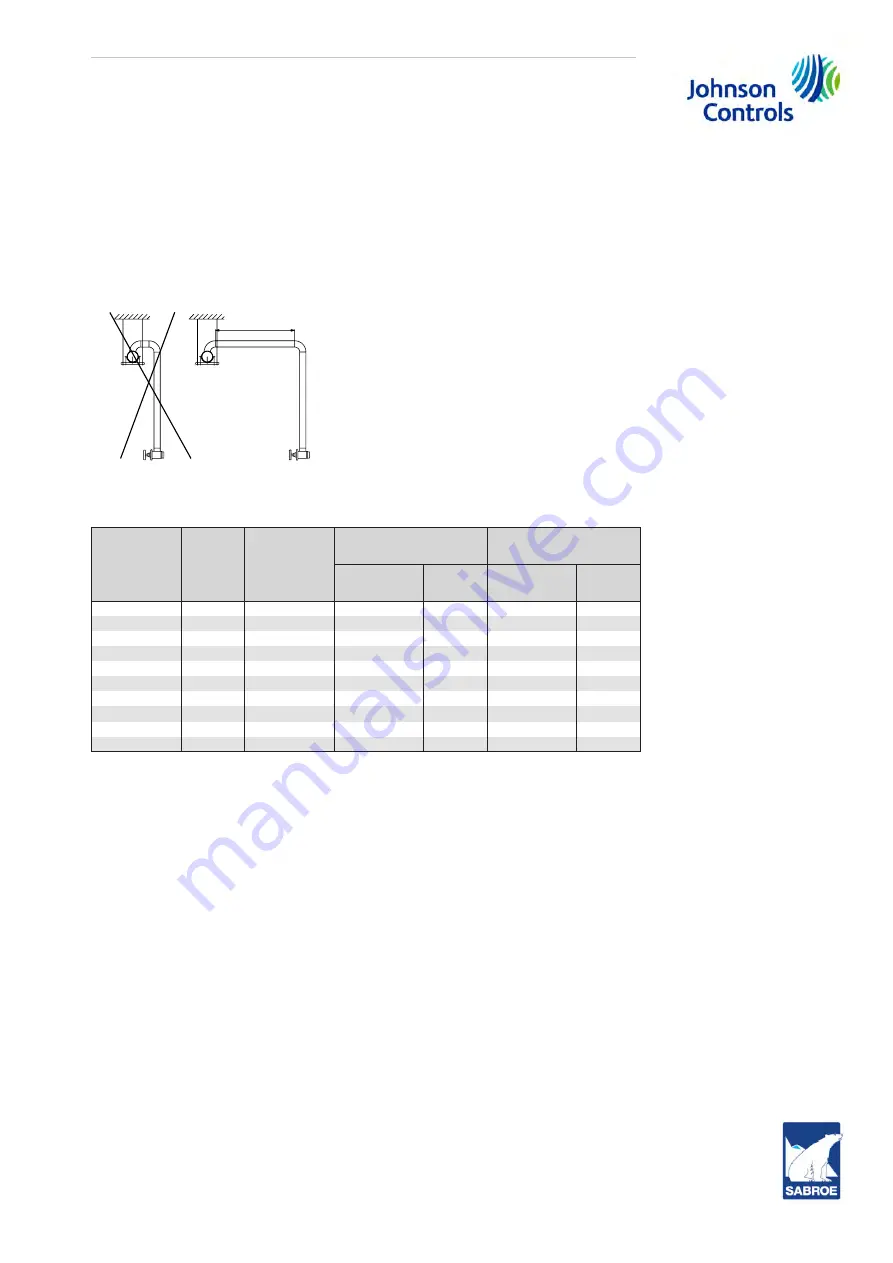
To avoid transmitting stress from piping connections between unit and plant, pipes must be laid
so as not to generate compressive stresses or tensile strains in the event of expansions or con-
tractions due to temperature changes. Steel pipes expand approx. 1 mm per metre per 100°C.
Johnson Controls Denmark recommends the pipe layout shown in example 2 of the sketch,
Fig. 85. Example 1 illustrates a pipe layout which is too rigid.
Fig. 85: Pipe layout
Sabroe
unit
Refer-
ence
model
RWF II
Compressor
model
Discharge flange to
separator flange
Suction flange
Bolt size
Torque
(Nm)
Bolt size
Torque
(Nm)
SAB 193 S
100
SGC 1913
M20 x 2.5
190
M20 x 2.5
298
SAB 193 L
134
SGC 1918
M20 x 2.5
190
M20 x 2.5
298
SAB 233 S
177
SGC 2313
M20 x 2.5
217
M20 x 2.5
298
SAB 233 L
222
SGC 2317
M20 x 2.5
217
M20 x 2.5
350
SAB 233 E
270
SGC 2321
M20 x 2.5
217
M22 x 2.5
350
SAB 283 S
316
SGC 2813
M22 x 2.5
312
M22 x 2.5
350
SAB 283 L
399
SGC 2817
M22 x 2.5
312
M22 x 2.5
400
SAB 283 E
480
SGC 2821
M22 x 2.5
312
M24 x 3.0
400
SAB 355 S
496
SGC 3511
M24 x 3.0
325
M30 x 3.5
475
SAB 283 X
546
SGC 2824
M22 x 2.5
325
M24 x 3.0
400
Table 48: Torque requirements
Note:
Based on:
a.
Gaskets-Garlock(R) Blue-Gard(R) 3300 and KLINGERSIL C-4430 (suction flange)
b.
Bolts-class 8.8 hex head bolts and stud bolts (suction flange), lightly oiled and clean
Chapter
5. Physical and connection data
includes dimension data and piping connections
descriptions.
Refrigerant connection to compressor and unit
The connecting pipe must be welded onto a connecting branch on a stop valve. In order to protect
the stop valve when welding, remove the insides of the valve. Do not put the insides back into the
valve until the weld has cooled off, see the instructions from the valve supplier.
The welding must be carried out according to the specifications and standards applying to the
plant in question.
Refrigerant connection to oil cooler
Connection dimensions as well as location of connecting branches are included in section
Connections to compressor unit
.
1
2
> 1.5 m
Summary of Contents for Sabroe SAB 193 L
Page 1: ...SAB 193 233 283 S A frame including ATEX Screw compressor units Engineering manual en ...
Page 2: ......
Page 169: ......


