background image

T606MSx-4 and T606MSx-4+PIR Series Multi-Stage Temperature and Humidity Controllers 
Installation Instructions 

5

Setup and Adjustments

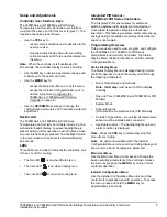
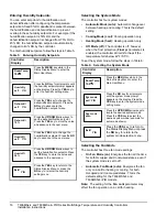
Controller User Interface Keys

The T606MSx-4 and T606MSx-4+PIR Series 
Temperature and Humidity Controller user interface 
consists of five keys on the front cover (Figure 7). The 
function of each key is as follows:

Use  the 

YES

 key to:

-

confirm menu selections and to advance to the 
next menu item.

-

stop the Status Display Menu from scrolling 
and to manually scroll to the next parameter on 
the menu.

Note:

When the controller is left unattended for 

45 seconds, the controller display resumes scrolling.

Use  the 

NO

 key to decline a parameter change and 

to advance to the next menu item.

Use  the 

MENU

 key to:

-

access the Main User Menu or exit the menu.

-

access the Installer Configuration Menu or to 
exit the menu (See 

Configuring the 

T606MSx-4 or T606MSx-4+PIR Series 
Controller

 on page 8.)

Use  the 

UP/DOWN

 arrow keys to change the 

configuration parameters and to activate a setpoint 
adjustment.

Backlit LCD

The T606MSx-4 and T606MSx-4+PIR Series 
Temperature and Humidity Controllers include a 2-line, 
8-character backlit display. Low-level backlighting is 
present during normal operation, and it brightens when 
any user interface key is pressed. The backlight returns 
to low level when the controller is left unattended for 
45 seconds.

LEDs

Three LEDs are included to indicate the fan status, call 
for heat, or call for cooling:

The fan LED 

 is on when the fan is on.

The heat LED 

 is on when heating is on.

The cool LED 

 is on when cooling is on.

Integrated PIR Sensor – 
T606MSx-4+PIR Series Controllers

The integrated PIR sensor allows for automatic 
switching between fully adjustable Occupied and 
Unoccupied temperature setpoints without user 
interaction. This feature generates incremental energy 
savings during scheduled occupied periods while the 
space is unoccupied.

Programming Overview

Three menus are used to view, program, and configure 
the T606MSx-4 and T606MSx-4+PIR Series 
Temperature and Humidity Controllers: the Status 
Display Menu, the Main User Menu, and the Installer 
Configuration Menu.

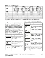
Status Display Menu

The Status Display Menu is displayed during normal 
controller operation, and continuously scrolls through 
the following parameters:

Room Temperature and Humidity

Note: %RH disp 

must be set to ON to display 

humidity.

Day and Time (T606MSP-4 and T606MSP-4+PIR 
Models)

System Mode

Schedule Status
(Occupied/Unoccupied/Override [PIR Models])

Outside Temperature – An outside air temperature 
sensor must be installed and connected.

Applicable Alarms – The backlight lights up as an 
alarm condition is displayed.

Note:

Press the 

YES

 key to temporarily stop this 

menu from scrolling.

Note:

An option is available within the Installer 

Configuration Menu to lock out the scrolling display and 
show only the Room Temperature parameter.

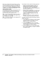
Main User Menu

Use the Main User Menu to access and change the 
basic operating parameters of the controller. Access 
the menu by pressing the 

MENU

 key during normal 

controller operation.

Installer Configuration Menu

Use the Installer Configuration Menu to set up the 
controller for application-specific operation. To access 
the menu, press and hold the 

MENU

 key for 

approximately 8 seconds.

Summary of Contents for T606MSN-4

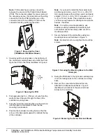
Page 1: ...er and open the controller as illustrated in Figure 1 IMPORTANT The T606MSx 4 and T606MSx 4 PIR Series Temperature and Humidity Controllers are intended to provide an input to equipment under normal operating conditions Where failure or malfunction of the controller could lead to personal injury or property damage to the controlled equipment or other property additional precautions must be designe...

Page 2: ...controller Note If you need to install the thermostat on an electrical junction box use 2 1 2 x 4 in 63 x 101 mm square boxes with mud ring covers and avoid smaller 1 1 2 x 4 in 38 x 101 mm square or 3 x 2 in 76 x 51 mm boxes This procedure ensures you have enough space for cabling and end of line devices if needed Note For surface mount applications use durable mounting hardware such as Molly bol...

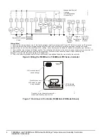
Page 3: ...re making electrical connections to avoid electric shock CAUTION Risk of Property Damage Do not apply power to the system before checking all wiring connections Short circuited or improperly connected wires may result in permanent damage to the equipment IMPORTANT Make all wiring connections in accordance with local national and regional regulations Do not exceed the electrical ratings of the T606...

Page 4: ...ccupancy of the electronic control card inside the equipment configure the relay parameter Aux Cont to the Normally Open N O setting A second relay can be added for additional occupancy input functions 3 The humidifier output uses a half bridge rectifier The control signal reference is the controller power supply common terminal C 4 Electromechanical contacts are used with the digital input Electr...

Page 5: ... is on The cool LED is on when cooling is on Integrated PIR Sensor T606MSx 4 PIR Series Controllers The integrated PIR sensor allows for automatic switching between fully adjustable Occupied and Unoccupied temperature setpoints without user interaction This feature generates incremental energy savings during scheduled occupied periods while the space is unoccupied Programming Overview Three menus ...

Page 6: ... includes a high limit sequence This sequence allows the use of a remote 0 to 10 VDC humidity sensor to keep the humidifier from saturating the supply air The remote sensor throttles the output of the Proportional plus Integral plus Derivative PID loop if the high limit sensor measures humidity in the duct over the high limit value 85 less the proportional band of the high limit PID loop If no sen...

Page 7: ...ed strategy If the controller is programmed to be Unoccupied the PIR function does not have an effect on the occupancy strategy The controller automatically switches the occupancy level between Occupied and Unoccupied as required when local movement is sensed In the Occupied mode if no movement is detected beyond the Unocc TM parameter setting the mode changes to Unoccupied Once movement is detect...

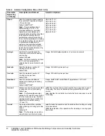
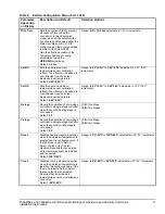
Page 8: ...splay Menu and when the message is displayed the backlight momentarily lights up The input can be configured to the Selection Options included in Table 2 Table 2 Installer Configuration Menu Part 1 of 6 Parameter Appearing on Display Description and Default Selection Options Pswrd Sets the protective access password to prevent unauthorized access to the Installer Configuration Menu Default 0 Note ...

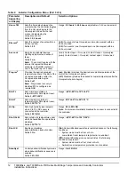
Page 9: ...ccess Clock Setting2 Access Access Access Permanent Hold2 Access No Access No Access Pwr del3 Sets the delay time period at controller powerup or each time power is removed and reapplied before any operation fan heating or cooling is authorized Also can be used to sequence the startup of multiple units in one location Default 10 0 sec Range 10 0 to 120 0 sec Frost pr Provides a minimum heating set...

Page 10: ...er of Heating cycles per hour Default 4 0 Range 3 0 to 8 0 cycles per hour Cool cph Sets the maximum number of Cooling cycles per hour Default 4 0 Range 3 0 or 4 0 cycles per hour Deadband Sets the minimum deadband between the heating and cooling setpoints Default 2 0F 1 0C Range 2 0F 1 0C to 4 0F 2 0C adjustable in 1 0F 0 5C increments Fan cont Determines how the fan is activated in response to a...

Page 11: ...5 0F 2 5C adjustable in 1 0F 0 5C increments H stage Reverts the operation of a two stage controller to a single stage controller when the second heating stage is not needed Default 2 0 1 0 One Stage 2 0 Two Stages C stage Reverts the operation of a two stage controller to a single stage controller when the second cooling stage is not needed Default 2 0 1 0 One Stage 2 0 Two Stages H lock Disables...

Page 12: ...cupied temperature at the start of the Occupied schedule off Disabled provides the desired occupied temperature after the Occupied schedule begins RH LT5 Sets minimum outside air temperature for RH setpoint reset Default 20 F 29 C Range 40 F 40 C to 15 F 9 5 C RH HT Sets maximum outside air temperature for RH setpoint reset Default 32 F 0 C Range 20 F 6 5 C to 55 F 13 C HL Sp Sets high humidity le...

Page 13: ...chedule menu display Any other setting enables schedules and the Schedule menu T606MSP 4 and T606MSP 4 PIR models 2 T606MSP 4 and T606MSP 4 PIR models 3 When adjusting the numeric value press the UP DOWN arrow key to change the value by single increments press and hold the UP DOWN arrow key to change the numeric value in increments of ten 4 When adjusting the temperature press the UP DOWN arrow ke...

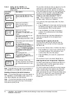
Page 14: ... Main User Menu 1 Press the NO key for all prompts until the Cancel ovrd prompt appears If the controller is in the override state this is the first prompt 2 Press the YES key to resume the programmed schedule The controller returns to the Status Display Menu Entering Permanent Temperature Setpoints The first prompt appearing in the Main User Menu of the controller when in the Occupied state sets ...

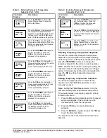
Page 15: ...ss the NO key for all prompts until the temperature setpoint prompt appears on the display it may be the first prompt Press the YES key to enter the temperature setting menu Press the YES key to change the Occupied cooling setpoint Press the NO key to advance to the Occupied heating setpoint menu Press the UP DOWN arrow keys to set the temperature Press the YES key to store the value and advance t...

Page 16: ...te The setting for the Fan cont parameter may affect the fan operation on a call for heating Table 5 Entering Humidity Setpoints Controller Display Description Press the MENU key while in the Status Display Menu to enter the Main User Menu Press the NO key for all prompts until the humidity setpoint prompt appears on the display Press the YES key to enter the humidity setting menu Press the YES ke...

Page 17: ...he fan mode prompt appears on the display Press the YES key to enter the fan mode setting menu Press the UP DOWN arrow keys to locate the desired fan mode Press the YES key to select the desired system mode example for smart mode shown Press the YES key to return to the Status Display Menu or press the NO key to return to the system mode selection menu RoomTemp 75 0 F Fan mode set Y N Fan mode Sma...

Page 18: ...s on the display Press the YES key to enter the scheduling menu Press the YES key to set the schedule for Monday or press the NO key to advance to Tuesday Table 8 Programming the Daily Schedule Two Event Part 2 of 2 Controller Display Description Exit Y N RoomTemp 75 0 F Schedule set Y N Monday set Y N Press the YES key to set the Occupied start time for Monday or press the NO key to advance to Tu...

Page 19: ...P M 1 Sunday 12 00 P M 1 12 00 P M 1 12 00 P M 1 12 00 P M 1 1 Programming different events to the same time for that day cancels those events and leaves the controller in the Unoccupied state Table 11 Setting the Day and Time Part 1 of 2 Controller Display Description Press the MENU key while in the Status Display Menu to enter the Main User Menu Press the NO key for all prompts until the clock s...

Page 20: ...edule hold menu has the following selections Permanent Occupied Hold occ hold This selection puts the controller into a permanent Occupied state via the Occupied setpoints Occupied hold appears in the Status Display Menu when this selection is active Permanent Unoccupied Hold This selection puts the controller into a permanent Unoccupied state via the Unoccupied setpoints Unoccup hold appears in t...

Page 21: ...ted on the wall Remote duct mounted humidity sensor may be used for remote return air humidity sensing with the sensor mounted on the return air duct or as a supply air humidity sensor used as a high limit protection 2 Additional TE 636xx x Series 10k ohm Johnson Controls Type II Thermistor Sensors are available refer to the TE 6300 Series Temperature Sensors Product Bulletin LIT 216320 for more d...

Page 22: ...ents Heating Control 40 0 F 4 5 C to 90 0 F 32 0 C Cooling Control 54 0 F 12 0 C to 100 0 F 38 0 C Accuracy Temperature 0 9F 0 5C at 70 0 F 21 0 C Typical Calibrated Humidity 5 RH from 30 to 70 RH at 50 to 90 F 10 to 32 C Minimum Deadband 2F 1C between Heating and Cooling Ambient Conditions Operating 32 to 122 F 0 to 50 C 95 RH Maximum Noncondensing Storage 22 to 122 F 30 to 50 C 95 RH Maximum Non...

Reviews: