background image

521271-UIM-D-1211

24

Johnson Controls Unitary Products

NOTES:

1. Airflow expressed in standard cubic feet per minute (CFM).
2. Motor voltage at 115 V.

3. Airflow through motor side (right side) may be slightly less than the data shown above.

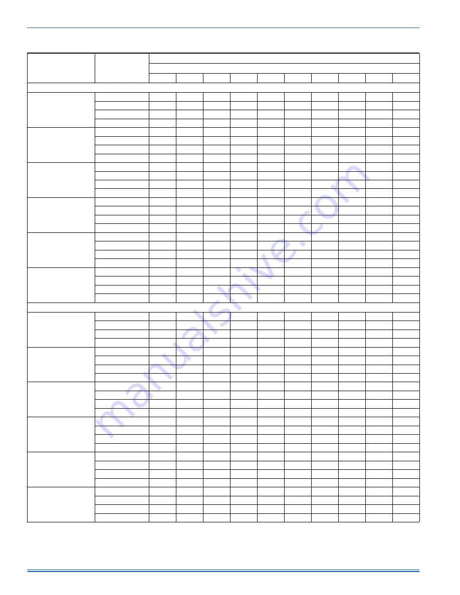
Table 14: 

Blower Performance CFM - Any Position - CFM

Models

Speed

Bottom Airflow Data (SCFM)

Ext. Static Pressure (in. H2O)

0.1

0.2

0.3

0.4

0.5

0.6

0.7

0.8

0.9

1.0

Bottom Return   (without filter)

060A12

High 

1358 1341 1319 1303 1275 1238 1190 1130 1062  943 

Medium 

High  1097 1083 1075 1064 1042 1024  997  962  906  821 

Medium 

Low  935 928 920 899 872 840 809 771 731 659 

Low 

800 779 763 736 711 687 657 622 584 529 

080B12

High 

1329 1307 1285 1247 1195 1143 1091 1027  927  806 

Medium 

High  994 1004 

1008 984 970 941 893 839 773 669 

Medium 

Low  786 790 782 781 761 743 726 685 630 540 

Low 

655 654 647 629 620 594 560 524 469 399 

080C16

High 

1881 1822 1783 1696 1602 1539 1465 1394 1267 1130 

Medium 

High  1553 1535 1492 1456 1408 1343 1279 1226 1113 1014 

Medium 

Low  1312 1286 1288 1260 1205 1143 1091 1029  966  841 

Low 

1169 

1166 

1128 

1098 

1069 

1032 987 909 835 747 

100C16

High 

2069 2014 1956 1885 1820 1748 1668 1577 1468 1362 

Medium 

High  1662 1656 1639 1608 1586 1544 1491 1421 1338 1204 

Medium 

1368 1371 1377 1376 1367 1334 1295 1250 1188 1104 

Low 

1016 1014 1018 1030 1012  996  975  944  898  852 

100C20

High 

2893 2774 2687 2589 2478 2376 2255 2120 1978 1824 

Medium 

High  2272 2243 2204 2169 2086 2018 1940 1842 1743 1602 

Medium 

Low  1765 1752 1737 1718 1674 1619 1561 1493 1437 1312 

Low 

1425 1380 1409 1378 1307 1274 1226 1180  1113 1025 

120C20

High 

2701 2620 2533 2429 2338 2227 2112 1993 1861 1706 

Medium 

High  2125 2083 2046 1994 1955 1901 1857 1737 1621 1497 

Medium 

Low  1664 1664 1647 1619 1580 1555 1468 1392 1332 1226 

Low 

1358 1339 1330 1318 1286 1235 1185 1141 1060  938 

Left Side Return (without filter)

060A12

High 

1406 1401 1394 1379 1338 1304 1261 1202 1135 1040 

Medium 

High  1129 1126 1107 1094 1076 1047 1010  966  921  843 

Medium 

Low  970 947 933 916 890 863 827 789 741 668 

Low 

834 809 797 768 740 710 677 634 586 534 

080B12

High 

1274 1285 1255 1239 1207 1158  1111  1049  979  830 

Medium 

High  975 974 968 960 948 923 879 823 756 672 

Medium 

Low  777 771 772 762 752 734 695 651 604 529 

Low 

647 634 623 610 602 588 552 506 457 381 

080C16

High 

1825 1781 1746 1695 1641 1587 1521 1429 1330 1184 

Medium 

High  1516 1493 1482 1464 1442 1411 1343 1275 1192 1035 

Medium 

1294 1297 1271 1238 1187 1120 1083 1028  979  851 

Low 

1126 1115 

1095 

1049 

1027 996 957 929 840 742 

100C16

High 

2009 1994 1933 1893 1836 1763 1691 1606 1508 1389 

Medium 

High  1523 1506 1521 1490 1466 1435 1393 1326 1241 1119 

Medium 

Low  1230 1249 1245 1230 1218 1195 1161 1120 1039  949 

Low 

1126 1115 

1095 

1049 

1027 996 957 929 840 742 

100C20

High 

2964 2886 2794 2707 2623 2522 2415 2281 2149 2012 

Medium 

High  2192 2178 2150 2109 2098 2007 1956 1888 1795 1671 

Medium 

Low  1699 1695 1706 1632 1612 1568 1519 1460 1392 1293 

Low 

1361 1356 1337 1304 1267 1243 1191 1149 1077  994 

120C20

High 

2828 2768 2699 2612 2524 2423 2308 2219 2118 1982 

Medium 

High  2085 2073 2042 2029 1967 1896 1893 1816 1717 1635 

Medium 

Low  1620 1631 1636 1593 1567 1557 1520 1476 1407 1263 

Low 

1322 1311 1302 1271 1241 1201 1162 1101 1042  979 

Summary of Contents for TM8T*MP

Page 1: ...ressure 22 Blower Performance CFM Any Position CFM 24 These high efficiency compact units employ induced combustion reli able hot surface ignition and high heat transfer aluminized tubular heat exchan...

Page 2: ...binet support the ends of the furnace rather than lifting by the cabinet flanges at the return air openings bottom or sides or supply air opening 13 When lifting the furnace it is acceptable to use th...

Page 3: ...the National Fire Protection Association Inc Batterymarch Park Quincy MA 02269 or for only the NFGC contact the American Gas Association 400 N Capital N W Washington DC 20001 or www NFPA org CANADA NS...

Page 4: ...onoxide detector with an alarm and battery back up is installed on the floor level where the gas equipment is to be installed In addition the installing plumber or gasfitter shall observe that a batte...

Page 5: ...otated down for shipment In order to use the flanges remove the screw holding an individual flange rotate the flange so it is in the upward position and reinstall the screw then repeat this for all 4...

Page 6: ...CE ASSEMBLY PC SERIES COILS These upflow coils are designed for installation on top of upflow fur naces only If the coil is used with a furnace of a different size use a 45 transition to allow proper...

Page 7: ...will be necessary to seal the edges of the bottom panel to the casing using tape or other appropriate gasket material to prevent air leakage BOTTOM RETURN AND ATTIC INSTALLATIONS Bottom return applica...

Page 8: ...one support at the supply end of the furnace one support located approximately in the center of the furnace near the blower shelf and the third support should be at the return end of the fur nace Mai...

Page 9: ...Entry Gas Pipe Entry Thermostat Wiring FRONT 14 1 1 5 23 SUPPLY END C 24 38 20 5 B Gas Pipe Entry Thermostat Wiring 33 A 5 Electrical Entry Vent Connection Outlet Vent Connection Outlet 4 Diameter Ou...

Page 10: ...e of the furnace using any of the gas pipe entry on both sides of the furnace Refer to Figure 12 All filters and mounting provision must be field supplied All installa tions must have a filter install...

Page 11: ...1 0 87 0 73 0 67 1100 3 2 2 7 2 4 41 0 0 80 0 66 0 61 2500 LP 9 8 8 2 7 5 93 2 LP 2 44 2 03 1 86 TABLE 6 Nominal Manifold Pressure Low Fire First Stage Manifold Pressures in w c First Stage Manifold P...

Page 12: ...wn in Figures 17 or 18 Electronic thermostats may require the common wire to be connected Apply strain relief to thermostat wires passing through cabinet If air condition ing equipment is installed us...

Page 13: ...Volt Hot Cool XFMR W First Stage Heat Part Number S1 2HU16700124 1 G L 8 9 T F L 8 9 T PT 8 9 ID MODELS Part Numbers SAP Legacy 265903 031 09168 2 C 24 Volt Common R 24 Volt Hot W W1 First Stage Heat...

Page 14: ...n Y First Stage Compressor O B Reversing Valve L Malfunction Light Y2 Second Stage Compressor G Fan PP32U70124 THERMOSTAT E Emergency Heat R 24 Volt Hot Heat XFMR RC 24 Volt Hot Cool XFMR AUX Auxiliar...

Page 15: ...e 20 If furnace staging is desired with two single stage furnaces on a com mon duct where the gas burner on the first furnace operates on W1 and the gas burner on the second furnace operates on W2 the...

Page 16: ...to any type of B BW or L vent connec tor and shall be connected to a factory built or masonry chimney The furnace shall not be connected to a chimney flue serving a sepa rate appliance designed to bu...

Page 17: ...sub tracting the blockage area of all fixed louvers grilles or screens from the gross area of the opening 2 Apertures in a fixed louver a grille or screen shall have no dimen sion smaller than 0 25 0...

Page 18: ...nal area as the free area of the air supply inlet opening to which it connects 4 The blocking effects of louvers grilles and screens must be given consideration in calculating free area If the free ar...

Page 19: ...ng placed into operation while all other appliances connected to the venting system are not in operation 1 Inspect the venting system for proper size and horizontal pitch Determine that there is no bl...

Page 20: ...natural gas input rate by clocking meter 1 Turn off all other gas appliances and pilots 2 Run furnace for a minimum of 3 minutes in heating operation 3 Measure time in sec for gas meter to complete 1...

Page 21: ...22 164 327 818 64 56 112 281 23 157 313 783 66 54 109 273 24 150 300 750 68 53 106 265 25 144 288 720 70 51 103 257 26 138 277 692 72 50 100 250 27 133 267 667 74 48 97 243 28 129 257 643 76 47 95 23...

Page 22: ...essure by adjusting gas valve regulator screw for the appropriate gas per the following 4 After the manifold pressure has been adjusted re calculate the furnace input to make sure you have not exceede...

Page 23: ...urnace but not so long that cold air is blown into the heated space The fan off timing may be adjusted by positioning the jumper on two of the four pins as shown in Figure 26 MANIFOLD PRESSURE U TUBE...

Page 24: ...Low 1425 1380 1409 1378 1307 1274 1226 1180 1113 1025 120C20 High 2701 2620 2533 2429 2338 2227 2112 1993 1861 1706 Medium High 2125 2083 2046 1994 1955 1901 1857 1737 1621 1497 Medium Low 1664 1664...

Page 25: ...warm up period the gas valve then opens the gas starts to flow ignition occurs and the flame sensor begins its sensing function The blower motor will energize 30 seconds after the gas valve opens if a...

Page 26: ...description of 5 Red Flashes and 11Red Flashes below If the main limit switch opens five times within a single call for heat the control will indicate 4 Red Flashes and will enter a one hour soft loc...

Page 27: ...ill flash three green flashes when the memory has been cleared then will resume the normal slow green flash after a five second pause SECTION X REPLACEMENT PARTS LIST DESCRIPTION MOTOR MOTOR DIRECT DR...

Page 28: ...with wiring material having a temperature ra ng of at least 221 F 105C 2 Blower motor speed connections shown are typical but may vary by model and application LEGENDE DS Commutateur de porte MOT Mote...

Reviews: