background image

505309-UIM-D-0511

10

Johnson Controls Unitary Products

HORIZONTAL APPLICATION

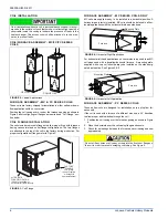
Horizontal Filters

Any branch duct (rectangular or round duct) attached to the plenum
must attach to the vertical plenum before the filter. The use of straps
and/or supports is required to support the weight of the external filter
box.

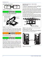
Downflow Filters

Downflow furnaces typically are installed with the filters located above
the furnace, extending into the return air plenum or duct. Any branch
duct (rectangular or round duct) attached to the plenum must attach to
the vertical plenum above the filter height.

Filter(s) may be located in the duct system external to the furnace using
an external duct filter box attached to the furnace plenum or at the end
of the duct in a return filter grille(s). The use of straps and/or supports is
required to support the weight of the external filter box.

SECTION IV: GAS PIPING

GAS SAFETY

GAS PIPING INSTALLATION

Properly sized wrought iron, approved flexible or steel pipe must be
used when making gas connections to the unit. If local codes allow the
use of a flexible gas appliance connection, always use a new listed con-
nector. Do not use a connector that has previously serviced another gas
appliance.

Some utility companies or local codes require pipe sizes larger than the
minimum sizes listed in these instructions and in the codes. The furnace
rating plate and the instructions in this section specify the type of gas
approved for this furnace - only use those approved gases. The instal-
lation of a drip leg and ground union is required. Refer to Figure 16.

The furnace must be isolated from the gas supply piping system by
closing its individual external manual shutoff valve during any pressure
testing of the gas supply piping system at pressures equal to or less
than 0.5 psig (3.5 kPa).

Gas piping may be connected from either side of the furnace using any
of the gas pipe entry knockouts on both sides of the furnace. Refer to
Figure 13.

All filters and mounting provision must be field supplied. All installa-
tions must have a filter installed.

An overpressure protection device, such as a pressure regulator,
must be installed in the gas piping system upstream of the furnace
and must act to limit the downstream pressure to the gas valve so it
does not exceed 0.5 psig [14" w.c. (3.48 kPa)]. Pressures exceeding
0.5 psig [14” w.c. (3.48 kPa)] at the gas valve will cause damage to
the gas valve, resulting in a fire or explosion or cause damage to the
furnace or some of its components that will result in property damage
and loss of life.

DANGER

 FIGURE 15:  

Gas Valve

Plan your gas supply before determining the correct gas pipe entry.
Use 90-degree service elbow(s), or short nipples and conventional
90-degree elbow(s) to enter through the cabinet access holes.

INLET

WRENCH
BOSS

INLET
PRESSURE
PORT

ON OFF
SWITCH

LOW STAGE REGULATOR
ADJUSTMENT

OUTLET

OUTLET
PRESSURE
PORT

VENT
PORT

HIGH STAGE REGULATOR
ADJUSTMENT

 FIGURE 16:  

Gas Piping

Upflow

Downflow

Horizontal

External
Manual
Shut-off
Valve

External
Manual
Shut-off
Valve

External Manual
Shut-off Valve

To Gas
Supply

To Gas
Supply

To Gas
Supply

To Gas
Supply

To Gas
Supply

To Gas
Supply

Drip
Leg

Drip
Leg

Drip
Leg

Drip
Leg

Drip Leg

Drip

Gas
Pipe

Gas
Valve

Gas
Pipe

Gas
Valve

Gas
Pipe

Gas
Valve

Ground
Union

Ground
Union

Ground
Union

Ground
Union

Ground
Union

Ground
Union

NOTE: Ground Union maybe installed inside or outside unit.

An accessible manual shutoff valve must be installed upstream of the
furnace gas controls and within 6 feet (1.8 m) of the furnace.

The gas valve body is a very thin casting that cannot take any exter-
nal pressure. Never apply a pipe wrench to the body of the gas valve
when installing piping. A wrench must be placed on the octagon hub
located on the gas inlet side of the valve. Placing a wrench to the
body of the gas valve will damage the valve causing improper opera-
tion and/or the valve to leak.

Summary of Contents for TM9T*MP

Page 1: ...drain vertical installation 16 Typical Combustion Pipe Drain Tee 17 Upflow Configuration 18 Downflow Configuration 19 Horizontal Left Configuration 20 Horizontal Right Configuration 21 Dimensions 23 H...

Page 2: ...rise per rating plate mark ing Means for providing outdoor air required for combustion Return air temperature maintained between 55 F 13 C and 80 F 27 C The air filter must be replaced upon substanti...

Page 3: ...listed below and all authorities having jurisdiction In the United States and Canada follow all codes and standards for the following using the latest edition available STEP 1 Safety US National Fuel...

Page 4: ...n FOR FURNACES INSTALLED IN THE COMMON WEALTH OF MASSACHUSETTS ONLY For all side wall horizontally vented gas fueled equipment installed in every dwelling building or structure used in whole or in par...

Page 5: ...is access cover shall be attached in such a manner as to prevent leaks DUCT FLANGES Four flanges are provided to attach ductwork to the furnace These flanges are rotated down for shipment In order to...

Page 6: ...uld always be installed on the side desig nated as top side See Figures 4 5 FURNACE ASSEMBLY PC SERIES COILS These upflow coils are designed for installation on top of upflow fur naces only If the coi...

Page 7: ...ace is to be installed on a flat solid surface this bottom panel will provide an adequate seal to prevent air leakage through the unused bottom opening However if the furnace is to be installed on a s...

Page 8: ...e one support at the supply end of the furnace one support located approximately in the center of the furnace near the blower shelf and the third support should be at the return end of the fur nace Ma...

Page 9: ...ombustion Air Inlet Gas Pipe Entry Electrical Entry Condensate Drain Optional Return Air Cutout Either side 29 5 For Cladded door add appoximately an additional 75 C SUPPLY END 56 56 20 B 3 23 8 56 Co...

Page 10: ...er side of the furnace using any of the gas pipe entry knockouts on both sides of the furnace Refer to Figure 13 All filters and mounting provision must be field supplied All installa tions must have...

Page 11: ...ABLE 6 Nominal Manifold Pressure Low Fire First Stage Manifold Pressures in w c First Stage Manifold Pressures kPa Altitude feet Altitude m 0 7999 8000 8999 9000 9999 0 2437 2438 2742 2743 3048 Gas He...

Page 12: ...ard on the ignition module as shown in Figures 18 or 19 Electronic thermostats may require the common wire to be connected Apply strain relief to thermostat wires passing through cabinet If air condit...

Page 13: ...C 24 Volt Hot Cool XFMR W First Stage Heat Part Number S1 2HU16700124 1 G L 8 9 T F L 8 9 T PT 8 9 ID MODELS Part Numbers SAP Legacy 265903 031 09168 2 C 24 Volt Common R 24 Volt Hot W W1 First Stage...

Page 14: ...Common Y First Stage Compressor O B Reversing Valve L Malfunction Light Y2 Second Stage Compressor G Fan PP32U70124 THERMOSTAT E Emergency Heat R 24 Volt Hot Heat XFMR RC 24 Volt Hot Cool XFMR AUX Au...

Page 15: ...typical application Figure 20 If furnace staging is desired with two furnaces on a common duct where the gas burner on the first furnace operates on W1 and the gas burner on the second furnace operate...

Page 16: ...sing right side opening when viewed from the front of the furnace For all 100 120 130K input furnaces the main drain is plumbed through the casing left side opening when viewed from the front of the f...

Page 17: ...a drain on the combustion air pipe as close to the furnace as possible as shown in Figure 23 This is true for all long horizontal venting in any furnace configuration This will prevent the condensate...

Page 18: ...ff so that no sagging loops will collect and hold condensate which will cause the furnace to not operate Shorten pressure switch hose Re route and shorten pressure switch hose Shorten rain gutter hose...

Page 19: ...ch hose to this position NOTE May require the longer hose that is provided with wider cabinets Move condensate drain hose to this position may exit either side of the cabinet Move rain gutter hose to...

Page 20: ...ose to this position NOTE May require the longer hose that is provided with wider cabinets Change condensate drain connection to the 90 fitting provided Move condensate drain hose to this position Mov...

Page 21: ...ting provided Move condensate drain hose to this position Move rain gutter hose to this position Change condensate drain connection to the 90 fitting provided Move condensate drain hose to this positi...

Page 22: ...BS pipe is to be used any joint where ABS pipe is joined to PVC pipe must be glued with cement that is approved for use with BOTH materials Metallic materials must not be used for venting or air intak...

Page 23: ...MBUSTION AIR VENTING FIGURE 28 Dimensions TABLE 9 Elbow Dimensions Elbow A Dimension 2 Standard 2 5 16 3 Standard 3 1 16 2 Sweep 3 1 4 3 Sweep 4 1 16 TABLE 10 Equivalent Length of Fittings Fitting Equ...

Page 24: ...quirements of the gas supplier 12 30 5 cm or in accordance with local installation codes and the requirements of the gas supplier F Clearance to outside corner 12 30 5 cm or in accordance with local i...

Page 25: ...om inside the building The vent for a single pipe system must be installed as specified in the venting section of these instructions with the vent terminating as shown in Figure 30 Each furnace must h...

Page 26: ...eric zone Refer to Figure 38 for attic and crawl space termination Only the combustion air intake may terminate in the attic The vent must terminate outside Outdoor Combustion Air Combustion Air Intak...

Page 27: ...ectangular shaped duct shall only be used when the required free area of the supply opening is 9 in2 58 06 cm2 or larger When a square or rectangular duct is used its small dimen sion shall not be les...

Page 28: ...ventilation VENT BLOWER ROTATION For ease of venting the vent blower may be rotated 90 in either direc tion For upflow installations the vent may exit through the top or either side of the cabinet For...

Page 29: ...proper input rate using natural gas with a heating value of 1030 BTU Ft3 38 4 MJ m3 If the heating value of your gas is significantly different it may be necessary to replace the orifices Verify natur...

Page 30: ...300 750 78 46 92 231 25 144 288 720 80 45 90 225 26 138 277 692 82 44 88 220 27 133 267 667 84 43 86 214 28 129 257 643 86 42 84 209 29 124 248 621 88 41 82 205 30 120 240 600 90 40 80 200 31 116 232...

Page 31: ...crews on main gas valve 2 Turn gas and electrical supplies on and follow the operating instruc tions to place the unit back in operation 3 Adjust manifold pressure by adjusting gas valve regulator scr...

Page 32: ...t be long enough to adequately cool the furnace but not so long that cold air is blown into the heated space The fan off timing may be adjusted by positioning the jumper on two of the four pins as sho...

Page 33: ...1232 1183 1143 1080 1003 871 798 120D20MP11 High 2341 2245 2153 2072 1977 1876 1769 1642 1506 1306 Medium High 2002 1952 1878 1823 1739 1657 1563 1458 1322 1185 Medium Low 1615 1579 1533 1473 1430 136...

Page 34: ...When the proper amount of combustion air is being provided the pressure switch will close the ignition control pro vides a 17 second ignitor warm up period the gas valve then opens the gas starts to...

Page 35: ...description of 5 Red Flashes and 11Red Flashes below If the main limit switch opens five times within a single call for heat the control will indicate 4 Red Flashes and will enter a one hour soft loc...

Page 36: ...will flash three green flashes when the memory has been cleared then will resume the normal slow green flash after a five second pause SECTION XII REPLACEMENT PARTS LIST DESCRIPTION MOTOR BLOWER COMBU...

Page 37: ...eed connections shown are typical but may vary by model and application LEGENDE DS Commutateur de porte MOT Moteur soufflerie CAP Capaciteur ROS Commutateur de roulement IDM D induct moteur FS Capteur...

Page 38: ...hange without notice Published in U S A 505309 UIM D 0511 Copyright 2011 by Johnson Controls Inc All rights reserved Supersedes 505309 UIM C 0910 Johnson Controls Unitary Products 5005 York Drive Norm...

Reviews: