background image


2    

VA-8122 Proportional Valve Actuator Product/Technical Bulletin


O

peration 

The actuator uses a reversible synchronous motor to 
accurately position the valve. The motor can reliably 
generate 22 pounds of force in either the Drive Down 
(DD) or Drive Up (DU) direction. 

Once the valve closes, a shutoff force builds up. When 
this force reaches 22 pounds, a lever within the 
actuator operates a force sensor that stops the motor. 
The constant load at the end of travel ensures tight 
valve seat shutoff and compensates for seat wear. 

Field calibration of shutoff is not required. The actuator 
maintains the shutoff force and its last position even if 
power is removed. 

Note: 

The valve stem can be positioned manually by 
turning the manual adjustment knob shown in 
Figure 2. Rotating the knob counterclockwise 
moves the valve stem up. 

Yoke/

Machine Screw

Lever
Plate

Drive
Screw

Jumpers

W1-W5

AUTOCAL

Pushbutton

Spade
Terminals (3)

LED

Circuit Board

+

2

4

C

O

M

V

D

C

/m

A

Stem Retainer/
Position Indicator

Manual
Adjustment
Knob


Figure 2: VA-8122 Components  

IMPORTANT: 

There are no internal mechanical 
stops in the actuator. Never drive 
the actuator unless it is installed on 
the proper valve body, or the 
actuator may be damaged. 
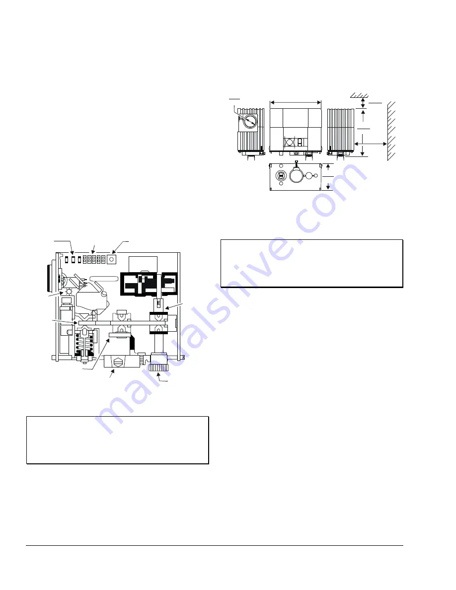
D

imensions 

See Figure 3 for actuator dimensions. 

5.00

127.0

2.50
63.5

0.87
22.2

4.50

114.3

0.50*

12.7

2.50*

63.5

* Required for cover
  removal clearance.


Figure 3: VA-8122 Dimensions, in. (mm)  

I

nstallation 

IMPORTANT: 

Dripping water must be prevented 
from entering the actuator housing, 
since this could damage the 
actuator. Do not cover the actuator 
with thermal insulating material. 

Note: 

The VA-8020-100 kit (ordered separately) is 
required if mounting to a VT Series Terminal 
Unit Valve. 

Kit Includes 


VA-8122 actuator 


VA-8020-605 stem retainer and clip kit 

Tools Required 


5/16 in. (8 mm) nut driver or 3/16 in. (5 mm) 
flat-blade screwdriver 


needle-nose pliers 


crescent wrench (to fit 1-1/4 in. bonnet 
adaptor nut) 

Summary of Contents for VA-8122

Page 1: ...r retrofits of VT Series Terminal Unit Valves with slotted stems and VB 5x39 Series Flare Valves Refer to the appropriate valve literature for more information Figure 1 VA 8122 1 Valve Actuator Features and Benefits q AUTOCAL Pushbutton Allows the actuator to define the control input range proportionally over the stroke q Simplified Setup and Adjustment Procedures Reduces installation costs q Sele...

Page 2: ...late Drive Screw Jumpers W1 W5 AUTOCAL Pushbutton Spade Terminals 3 LED Circuit Board 24 COM VDC mA Stem Retainer Position Indicator Manual Adjustment Knob Figure 2 VA 8122 Components IMPORTANT There are no internal mechanical stops in the actuator Never drive the actuator unless it is installed on the proper valve body or the actuator may be damaged Dimensions See Figure 3 for actuator dimensions...

Page 3: ...t adaptor nut making sure the yoke is flush with the surface of the nut Note If the valve stem is touching the coupler and preventing a flush contact use the manual adjustment knob shown in Figure 4 to reposition the coupler 5 Secure the actuator to the valve bonnet by tightening the hex head machine screw provided 6 Place the stem retainer and coupling clip over the valve stem so the lower shorte...

Page 4: ...he input signal is determined by the position of Jumpers W3 W4 and W5 See Table 1 and Table 2 Table 1 Jumper Settings W5 W4 W3 W2 W1 Shown in Factory Default Settings DD Drive Down Drive Up DU 6 9 VDC Current Input mA VDC Voltage Input The 6 9 VDC position of Jumper W5 overrides Jumper W3 0 10 VDC 0 20 mA 2 10 VDC 4 20 mA 0 10 VDC 0 20 VDC Table 2 Available Input Control Signal vs Input Jumpers Co...

Page 5: ...llation of the actuator This mode allows the actuator to define the control input range proportionally over the valve stroke stored in nonvolatile memory retains data when power is lost or removed Note Once calibrated it is not necessary to recalibrate if a jumper is changed To activate the AUTOCAL mode depress the AUTOCAL pushbutton for approximately 3 seconds until the LED turns off The actuator...

Page 6: ...osition Terminal Block Controller Input Signal 24 VAC Supply VDC mA 24 VAC COM Common Figure 8 VA 8122 Wiring IMPORTANT Install all the quick connect terminals in the same direction to each other to prevent the terminals from shorting See Figure 9 Figure 9 Orientation of Terminals Input lines to the actuator must be wired correctly for the valve to move in the proper direction Refer to the specifi...

Page 7: ...00 Series bronze valves The VA 8122 is also available for retrofitting VG7000 Series bronze valves VT Series Terminal Unit Valves with slotted stems and VB 5x39 Series Flare Valves Refer to the AV 8122 Series Proportional Control Actuated Valve Product Technical Bulletin FAN 977 or 1628 3 and the VG7000 Series Bronze Valves ANSI Class 250 PN16 Body Size 1 2 through 2 inch DN15 to DN50 Product Tech...

Page 8: ... Valve Media Temperature Water 195 F 90 C maximum Steam Actuator is not rated for this application Dimensions H x W x D 4 5 x 5 0 x 2 5 in 114 x 127 x 64 mm Shipping Weight 1 6 lb 0 74 kg Agency Compliance UL 873 Recognized File E27734 Guide XAPX2 CSA C22 2 No 139 Certified File LR85083 Class 3221 02 The performance specifications are nominal and conform to acceptable industry standards For applic...

Reviews: