background image


VA-8122 Proportional Valve Actuator Product/Technical Bulletin

    3 

M

ounting 

IMPORTANT: 

Do not use on valves having a 
stroke over 5/16 in. Travel beyond 
5/16 in. will damage the actuator or 
prevent complete shutoff. 

Note: 

In horizontal piping applications, it is 
recommended that the valve be mounted 
within 85° of the upright position. When 
mounted in vertical piping, the valve must be 
protected from moisture. 

Unpack the actuator and proceed as follows: 

1.  Remove the actuator cover by pressing inward on 

the plastic tabs while sliding the cover up and 
forward. 

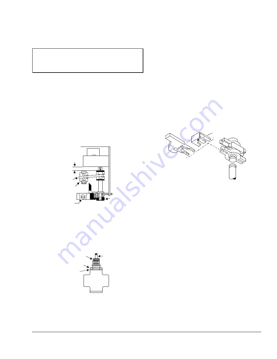
2.  Make sure that the lever plate is within 1/4 in. 

(6.4 mm) of the upper stop. (See Figure 4.) 

Lever Plate

Approximately

1/4 in.

Coupler

Yoke/

Machine Screw

Manual

Adjustment

Knob


Figure 4: Plate Position 


3.  For VT valves, thread the bonnet adaptor nut 

(included in the VA-8020-100 kit) onto the 
valve bonnet shown in Figure 5, and tighten with a 
wrench until it is snug. 

Bonnet

Adaptor Nut

Packing

Nut

Valve

Bonnet

Stem


Figure 5: Valve Bonnet Adaptor 

4.  Position the actuator yoke on the bonnet adaptor 

nut, making sure the yoke is flush with the surface 
of the nut. 

Note: 

If the valve stem is touching the coupler and 
preventing a flush contact, use the manual 
adjustment knob (shown in Figure 4) to 
reposition the coupler. 

5.  Secure the actuator to the valve bonnet by 

tightening the hex-head machine screw provided. 

6.  Place the stem retainer and coupling clip over the 

valve stem, so the lower (shorter) portion of the 
coupling clip is positioned in the locking groove on 
the valve stem as shown in Figure 6. 

Valve Stem

Coupler

Coupling Clip

Stem

Retainer

Lower Portion

of Clip


Figure 6: VA-8020-605 Stem Retainer and Clip Kit 

Note: 

The extended portion of the stem retainer 
must be located on the right so that it lines up 
in the window of the cover. It may be 
necessary to pull the valve stem up to meet 
the coupler or to rotate the manual adjustment 
knob (shown in Figure 4) clockwise to run the 
coupler down. 

7.  Push the white plastic stem retainer until the 

coupling clip moves forward into the groove, and 
the retainer locks the clip in place. 

8.  Verify that the valve stem is located at the back of 

the groove by examining the connection. 

To remove the coupling clip, use pliers to grip the stem 
retainer and pull outward. (See Figure 6.) 

Summary of Contents for VA-8122

Page 1: ...r retrofits of VT Series Terminal Unit Valves with slotted stems and VB 5x39 Series Flare Valves Refer to the appropriate valve literature for more information Figure 1 VA 8122 1 Valve Actuator Features and Benefits q AUTOCAL Pushbutton Allows the actuator to define the control input range proportionally over the stroke q Simplified Setup and Adjustment Procedures Reduces installation costs q Sele...

Page 2: ...late Drive Screw Jumpers W1 W5 AUTOCAL Pushbutton Spade Terminals 3 LED Circuit Board 24 COM VDC mA Stem Retainer Position Indicator Manual Adjustment Knob Figure 2 VA 8122 Components IMPORTANT There are no internal mechanical stops in the actuator Never drive the actuator unless it is installed on the proper valve body or the actuator may be damaged Dimensions See Figure 3 for actuator dimensions...

Page 3: ...t adaptor nut making sure the yoke is flush with the surface of the nut Note If the valve stem is touching the coupler and preventing a flush contact use the manual adjustment knob shown in Figure 4 to reposition the coupler 5 Secure the actuator to the valve bonnet by tightening the hex head machine screw provided 6 Place the stem retainer and coupling clip over the valve stem so the lower shorte...

Page 4: ...he input signal is determined by the position of Jumpers W3 W4 and W5 See Table 1 and Table 2 Table 1 Jumper Settings W5 W4 W3 W2 W1 Shown in Factory Default Settings DD Drive Down Drive Up DU 6 9 VDC Current Input mA VDC Voltage Input The 6 9 VDC position of Jumper W5 overrides Jumper W3 0 10 VDC 0 20 mA 2 10 VDC 4 20 mA 0 10 VDC 0 20 VDC Table 2 Available Input Control Signal vs Input Jumpers Co...

Page 5: ...llation of the actuator This mode allows the actuator to define the control input range proportionally over the valve stroke stored in nonvolatile memory retains data when power is lost or removed Note Once calibrated it is not necessary to recalibrate if a jumper is changed To activate the AUTOCAL mode depress the AUTOCAL pushbutton for approximately 3 seconds until the LED turns off The actuator...

Page 6: ...osition Terminal Block Controller Input Signal 24 VAC Supply VDC mA 24 VAC COM Common Figure 8 VA 8122 Wiring IMPORTANT Install all the quick connect terminals in the same direction to each other to prevent the terminals from shorting See Figure 9 Figure 9 Orientation of Terminals Input lines to the actuator must be wired correctly for the valve to move in the proper direction Refer to the specifi...

Page 7: ...00 Series bronze valves The VA 8122 is also available for retrofitting VG7000 Series bronze valves VT Series Terminal Unit Valves with slotted stems and VB 5x39 Series Flare Valves Refer to the AV 8122 Series Proportional Control Actuated Valve Product Technical Bulletin FAN 977 or 1628 3 and the VG7000 Series Bronze Valves ANSI Class 250 PN16 Body Size 1 2 through 2 inch DN15 to DN50 Product Tech...

Page 8: ... Valve Media Temperature Water 195 F 90 C maximum Steam Actuator is not rated for this application Dimensions H x W x D 4 5 x 5 0 x 2 5 in 114 x 127 x 64 mm Shipping Weight 1 6 lb 0 74 kg Agency Compliance UL 873 Recognized File E27734 Guide XAPX2 CSA C22 2 No 139 Certified File LR85083 Class 3221 02 The performance specifications are nominal and conform to acceptable industry standards For applic...

Reviews: