


4
VA-8122 Proportional Valve Actuator Product/Technical Bulletin
C
alibration
The actuator drives in proportion to the amount of
change in the input control signal. It accepts the input
control signal ranges by means of jumpers. Electrical
connections for the control input are made via spade
terminals that are mounted on the circuit board located
under the actuator’s cover. (See Figure 2 for the
location of the calibration components.)
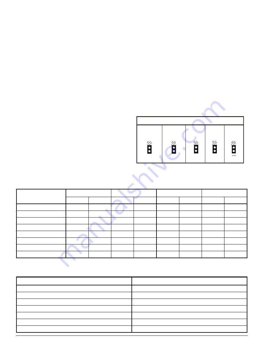
Jumpers
The type of input control signal is determined by the
position of Jumper W1. When Jumper W1 is in the
VDC position (factory setting), the input signal is
DC voltage. When Jumper W1 is in the mA position,
the signal changes to current input. The direction of
action, either DD (factory setting) or DU, is selected
with Jumper W2. The range of the input signal is
determined by the position of Jumpers W3, W4,
and W5. (See Table 1 and Table 2.)
Table 1: Jumper Settings
W5
*
W4
W3
W2
W1
Shown in Factory (Default) Settings
DD
(Drive Down)
(Drive Up)
DU
6-9 VDC
(Current Input)
mA
VDC
(Voltage Input)
* The 6-9 VDC position of Jumper W5 overrides Jumper W3.
0-10 VDC
(0-20 mA)
2-10 VDC
(4-20 mA)
0-10 VDC
0-20 VDC
Table 2: Available Input Control Signal vs. Input Jumpers
Control Signal
Jumper W1
Jumper W3
Jumper W4
Jumper W5*
VDC
mA
0-10
2-10
0-10
0-20
—
6-9
0 to 10 VDC
X
X
X
X
2 to 10 VDC
X
X
X
X
6 to 9 VDC
X
X
X
X
12 to 18 VDC
X
X
X
X
0 to 20 VDC
X
X
X
X
4 to 20 VDC
X
X
X
X
0 to 20 mA
X
X
X
X
4 to 20 mA
X
X
X
X
* When Jumper W5 is in the 6 to 9 VDC position, it overrides Jumper W3.
Table 3: Calibration Values for the AV-8122
Control Signal
Values (All Nominal)
0 to 10 VDC
0.7 to 9.3 VDC
2 to 10 VDC
2.6 to 9.4 VDC
6 to 9 VDC
6.5 to 8.5 VDC
0 to 20 VDC
1.4 to 18.6 VDC
4 to 20 VDC
5.2 to 18.8 VDC
0 to 20 mA
1.4 to 18.6 mA
4 to 20 mA
5.2 to 18.8 mA


