background image


6    

VA-8122 Proportional Valve Actuator Product/Technical Bulletin


W

iring 

!

 CAUTION: 

Risk of Electric Shock. 

Disconnect the power supply before making 
electrical connections to avoid electric shock. 

MISE EN GARDE : Risque de décharge 
électrique. 

Débrancher l'alimentation avant de réaliser tout 
raccordement électrique afin d'éviter tout risque de 
décharge électrique. 

!

 CAUTION:  Risk of Property Damage. 

Do not apply power to the system before checking all 
wiring connections. Short circuited or improperly 
connected wires may result in permanent damage to 
the equipment. 

MISE EN GARDE : Risque de dégâts matériels. 

Ne pas mettre le système sous tension avant d'avoir 
vérifié tous les raccords de câblage. Des fils formant 
un court-circuit ou connectés de façon incorrecte 
risquent d'endommager irrémédiablement 
l'équipement.


IMPORTANT: 

Make all wiring connections in 
accordance with the National 
Electrical Code and local 
regulations. 

When a 24 VAC power signal is applied to the +24 and 
COM terminals, the VA-8122 accepts a DC voltage 
input control signal or current input signal at the 
VDC/mA (+) and COM (–) terminals. 

The VA-8122 wiring connections are made to the 
tab receptacles shown in Figure 8. Use either the 
quick-connect terminals shown in Figure 9 or an 
M9000-105 Pluggable (3-position) Terminal Block. 

Controller

Input Signal

24 VAC

Supply

VDC/mA

+24 VAC

COM

(Common)

+

~


Figure 8: VA-8122 Wiring  
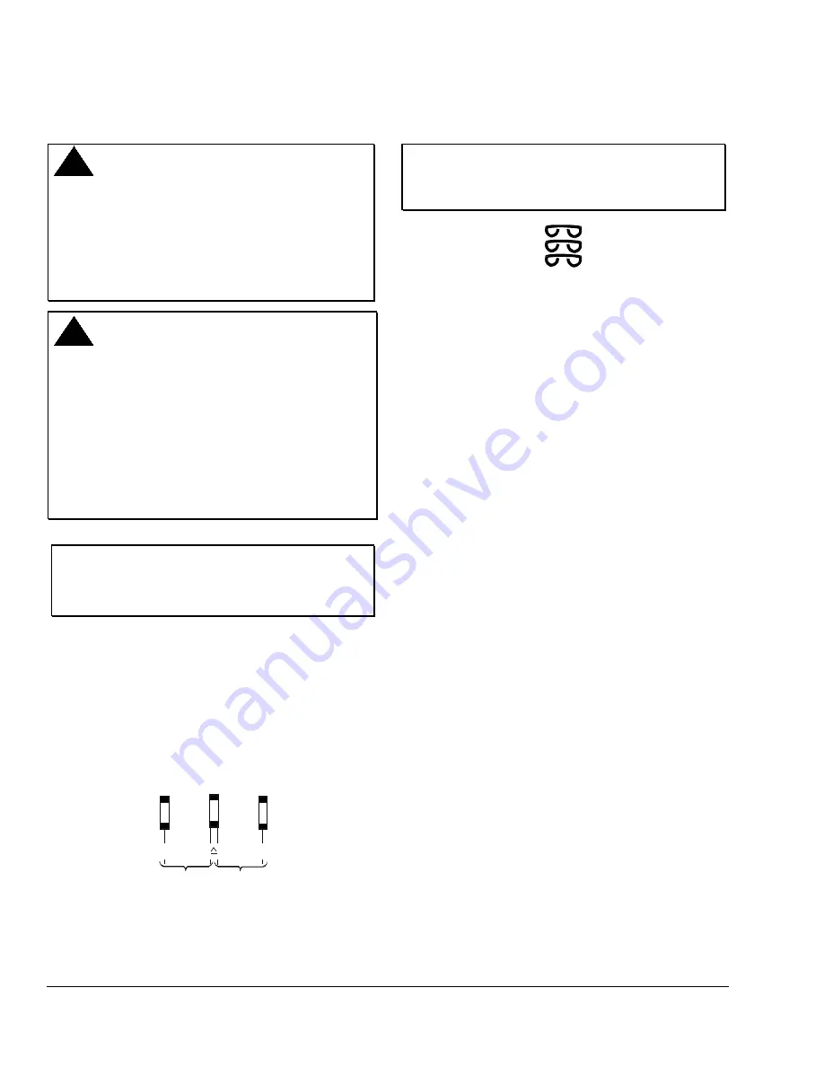
 

IMPORTANT: 

Install all the quick-connect 
terminals in the same direction to 
each other to prevent the terminals 
from shorting. (See Figure 9.) 


Figure 9: Orientation of Terminals 


Input lines to the actuator must be wired correctly for 
the valve to move in the proper direction. (Refer to the 
specific controller wiring instructions as needed.) Wire 
the actuator as follows: 

1.  Push in the two tabs on the side of the actuator 

cover and lift and remove it. 

2.  Insert the controller leads through the plate on the 

side of the actuator. 

3.  Make the wiring connections to the terminals as 

shown in Figure 8. 

C

ommissioning 

Field calibration of the force sensor is not required. 

If power is removed from the VA-8122, the valve stem 
remains in its intermediate position until power is 
reapplied. 

If the control signal to the actuator is lost, the valve 
stem moves to the zero input signal position: 
valve stem up in DD mode or down in DU mode. 

Checkout 

The VA-8122 is factory set as follows: 


Jumper W1 in the VDC position 


Jumper W2 in the DD position 


Jumpers W3 and W4 in the 0 to 10 VDC position 


Jumper W5 in the "—" position 

If this is the intended operation, proceed as follows: 

1.  Depress the AUTOCAL pushbutton. (Actuator 

drives to the DU end-stop, the DD end-stop, and 
then returns to the setpoint.) 

2.  Provide minimum control signal. (Actuator drives 

the valve stem up, and the motor stops.) 

Summary of Contents for VA-8122

Page 1: ...r retrofits of VT Series Terminal Unit Valves with slotted stems and VB 5x39 Series Flare Valves Refer to the appropriate valve literature for more information Figure 1 VA 8122 1 Valve Actuator Features and Benefits q AUTOCAL Pushbutton Allows the actuator to define the control input range proportionally over the stroke q Simplified Setup and Adjustment Procedures Reduces installation costs q Sele...

Page 2: ...late Drive Screw Jumpers W1 W5 AUTOCAL Pushbutton Spade Terminals 3 LED Circuit Board 24 COM VDC mA Stem Retainer Position Indicator Manual Adjustment Knob Figure 2 VA 8122 Components IMPORTANT There are no internal mechanical stops in the actuator Never drive the actuator unless it is installed on the proper valve body or the actuator may be damaged Dimensions See Figure 3 for actuator dimensions...

Page 3: ...t adaptor nut making sure the yoke is flush with the surface of the nut Note If the valve stem is touching the coupler and preventing a flush contact use the manual adjustment knob shown in Figure 4 to reposition the coupler 5 Secure the actuator to the valve bonnet by tightening the hex head machine screw provided 6 Place the stem retainer and coupling clip over the valve stem so the lower shorte...

Page 4: ...he input signal is determined by the position of Jumpers W3 W4 and W5 See Table 1 and Table 2 Table 1 Jumper Settings W5 W4 W3 W2 W1 Shown in Factory Default Settings DD Drive Down Drive Up DU 6 9 VDC Current Input mA VDC Voltage Input The 6 9 VDC position of Jumper W5 overrides Jumper W3 0 10 VDC 0 20 mA 2 10 VDC 4 20 mA 0 10 VDC 0 20 VDC Table 2 Available Input Control Signal vs Input Jumpers Co...

Page 5: ...llation of the actuator This mode allows the actuator to define the control input range proportionally over the valve stroke stored in nonvolatile memory retains data when power is lost or removed Note Once calibrated it is not necessary to recalibrate if a jumper is changed To activate the AUTOCAL mode depress the AUTOCAL pushbutton for approximately 3 seconds until the LED turns off The actuator...

Page 6: ...osition Terminal Block Controller Input Signal 24 VAC Supply VDC mA 24 VAC COM Common Figure 8 VA 8122 Wiring IMPORTANT Install all the quick connect terminals in the same direction to each other to prevent the terminals from shorting See Figure 9 Figure 9 Orientation of Terminals Input lines to the actuator must be wired correctly for the valve to move in the proper direction Refer to the specifi...

Page 7: ...00 Series bronze valves The VA 8122 is also available for retrofitting VG7000 Series bronze valves VT Series Terminal Unit Valves with slotted stems and VB 5x39 Series Flare Valves Refer to the AV 8122 Series Proportional Control Actuated Valve Product Technical Bulletin FAN 977 or 1628 3 and the VG7000 Series Bronze Valves ANSI Class 250 PN16 Body Size 1 2 through 2 inch DN15 to DN50 Product Tech...

Page 8: ... Valve Media Temperature Water 195 F 90 C maximum Steam Actuator is not rated for this application Dimensions H x W x D 4 5 x 5 0 x 2 5 in 114 x 127 x 64 mm Shipping Weight 1 6 lb 0 74 kg Agency Compliance UL 873 Recognized File E27734 Guide XAPX2 CSA C22 2 No 139 Certified File LR85083 Class 3221 02 The performance specifications are nominal and conform to acceptable industry standards For applic...

Reviews: