background image


VA-8122 Proportional Valve Actuator Product/Technical Bulletin

    7 

3.  Provide maximum control signal. (Actuator drives 

the valve stem down, and the motor stops.) 

4.  Observe the vertical movement of the indicator 

within the actuator window to ensure proper 
positioning. The installation is complete. 

Note: 

If factory settings are to be changed, see the 

Calibration

 section. 


O

rdering Information 

Field repairs must not be made. To order a 
proportional valve actuator, contact the nearest 
Johnson Controls representative and specify product 
code number VA-8122-1. 

Actuator Combinations 

The VA-8122-1 is available factory coupled to 1/2 in. 
or 3/4 in. VG7000 Series bronze valves. The VA-8122 
is also available for retrofitting VG7000 Series bronze 
valves, VT Series Terminal Unit Valves (with slotted 
stems), and VB-5x39 Series Flare Valves. Refer to the 

AV-8122 Series Proportional Control Actuated Valve 
Product/Technical Bulletin


(FAN 977 or 1628.3

), and 

the 

VG7000 Series Bronze Valves ANSI Class 250 

(PN16) Body Size 1/2 through 2 inch (DN15 to DN50) 
Product/Technical Bulletin


(FAN 977, 125, or 1628.3) 

for available configurations. Accessories for the 
VA-8122 can be found in Table 5. 

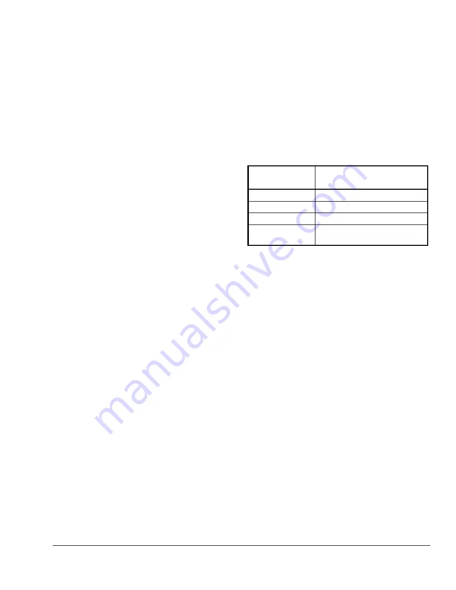
Table 5: Accessories 

Product 
Code Number 

Description 

VA-8020-100


Mounting kit for VT Series valves


VA-8020-601 

Replacement cover only 

VA-8020-605* 

Stem retainer and clip kit 

M9000-105 

Pluggable 3-position terminal 
block 

*  One kit is included with the actuator. If ordered separately, 

it must be ordered in multiples of five. 

Summary of Contents for VA-8122

Page 1: ...r retrofits of VT Series Terminal Unit Valves with slotted stems and VB 5x39 Series Flare Valves Refer to the appropriate valve literature for more information Figure 1 VA 8122 1 Valve Actuator Features and Benefits q AUTOCAL Pushbutton Allows the actuator to define the control input range proportionally over the stroke q Simplified Setup and Adjustment Procedures Reduces installation costs q Sele...

Page 2: ...late Drive Screw Jumpers W1 W5 AUTOCAL Pushbutton Spade Terminals 3 LED Circuit Board 24 COM VDC mA Stem Retainer Position Indicator Manual Adjustment Knob Figure 2 VA 8122 Components IMPORTANT There are no internal mechanical stops in the actuator Never drive the actuator unless it is installed on the proper valve body or the actuator may be damaged Dimensions See Figure 3 for actuator dimensions...

Page 3: ...t adaptor nut making sure the yoke is flush with the surface of the nut Note If the valve stem is touching the coupler and preventing a flush contact use the manual adjustment knob shown in Figure 4 to reposition the coupler 5 Secure the actuator to the valve bonnet by tightening the hex head machine screw provided 6 Place the stem retainer and coupling clip over the valve stem so the lower shorte...

Page 4: ...he input signal is determined by the position of Jumpers W3 W4 and W5 See Table 1 and Table 2 Table 1 Jumper Settings W5 W4 W3 W2 W1 Shown in Factory Default Settings DD Drive Down Drive Up DU 6 9 VDC Current Input mA VDC Voltage Input The 6 9 VDC position of Jumper W5 overrides Jumper W3 0 10 VDC 0 20 mA 2 10 VDC 4 20 mA 0 10 VDC 0 20 VDC Table 2 Available Input Control Signal vs Input Jumpers Co...

Page 5: ...llation of the actuator This mode allows the actuator to define the control input range proportionally over the valve stroke stored in nonvolatile memory retains data when power is lost or removed Note Once calibrated it is not necessary to recalibrate if a jumper is changed To activate the AUTOCAL mode depress the AUTOCAL pushbutton for approximately 3 seconds until the LED turns off The actuator...

Page 6: ...osition Terminal Block Controller Input Signal 24 VAC Supply VDC mA 24 VAC COM Common Figure 8 VA 8122 Wiring IMPORTANT Install all the quick connect terminals in the same direction to each other to prevent the terminals from shorting See Figure 9 Figure 9 Orientation of Terminals Input lines to the actuator must be wired correctly for the valve to move in the proper direction Refer to the specifi...

Page 7: ...00 Series bronze valves The VA 8122 is also available for retrofitting VG7000 Series bronze valves VT Series Terminal Unit Valves with slotted stems and VB 5x39 Series Flare Valves Refer to the AV 8122 Series Proportional Control Actuated Valve Product Technical Bulletin FAN 977 or 1628 3 and the VG7000 Series Bronze Valves ANSI Class 250 PN16 Body Size 1 2 through 2 inch DN15 to DN50 Product Tech...

Page 8: ... Valve Media Temperature Water 195 F 90 C maximum Steam Actuator is not rated for this application Dimensions H x W x D 4 5 x 5 0 x 2 5 in 114 x 127 x 64 mm Shipping Weight 1 6 lb 0 74 kg Agency Compliance UL 873 Recognized File E27734 Guide XAPX2 CSA C22 2 No 139 Certified File LR85083 Class 3221 02 The performance specifications are nominal and conform to acceptable industry standards For applic...

Reviews: