WT-ROUTER Router Installation Instructions
2
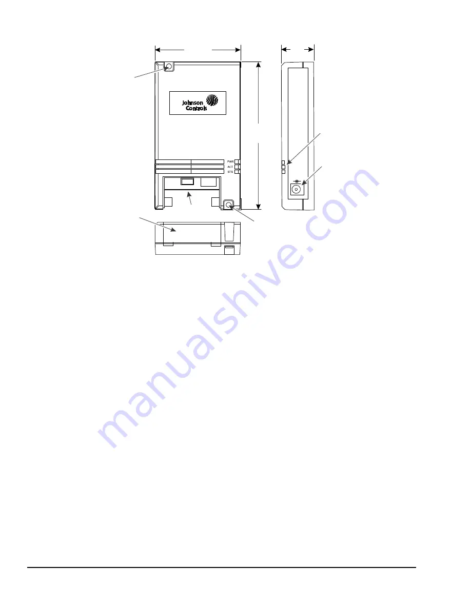
Status Indication LEDs
The WT-ROUTER communicates status using the
following LEDs:
•
STS LED—Blinking indicates that the router is
connected to the wireless network with only one
active path. This LED remains on if two or more
wireless paths exist.
•
ACT LED—On steady indicates that there is RF
traffic at the device.
•
PWR LED—On steady indicates that power is
applied to the device.
Installation
Follow these guidelines when installing the
WT-ROUTER Router:
•
Transport the router in the original container to
minimize vibration and shock damage.
•
Verify that all the parts shipped with the router.
•
Do not drop the router or subject it to physical
shock.
•
Do not attempt to open the router housing or repair
the device; the router is not user serviceable.
Parts Included
•
one WT-ROUTER Router
•
one power adaptor
•
one installation instructions sheet
Mounting
The WT-ROUTER Router can be surface mounted
using two field-furnished screws. Mount the unit to the
surface at the two mounting hole locations on the
device (Figure 1).
The router can also be secured to a bracket above a
drop ceiling using field-furnished tie wraps.
Location Considerations
The WT-ROUTER Router must remain powered up at
all times to operate properly. Choose an installation
location where the power supply cannot be accidentally
unplugged. An ideal location for the router is above a
drop ceiling with a dedicated power source.
Figure 1: WT-ROUTER Router
Physical Features and Dimensions, in. (mm)
W
T
-R
out
e
r
OFF/ON
PROGRAM
4-21/32
(118)
1
(25)
F
IG:
wt
_
rt
r
2-23/32
(69)
LED
Indicators
Connector Panel
Access Cover
Mounting Hole
(Two Locations)
OFF/ON
Switch
Mounting Hole
(Two Locations)
Power
Connector


