JOHNSON CONTROLS
237
SECTION 8 - MICROPANEL
FORM 201.23-NM2
ISSUE DATE: 3/9/2015
8
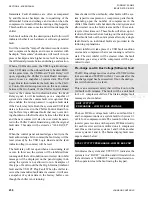
Pre-charge DC Bus Voltage Imbalance
(Software) Fault
The 1/2 DC Bus voltage magnitude must remain with-
in plus or minus 100VDC of the total DC Bus voltage
divided by two during the pre-charge interval. If not,
the unit/system shall shut down on a fault.
This safety will lock out on the 1st fault. The fault will
be a unit fault for 2 or 3 compressor units. The Status
display fault message is shown below:
UNIT YYYYYYYY
PRECHARGE - DC BUS VOLTAGE IMBALANCE
The fault will be a System 1/3 or 2/4 fault for 4 com-
pressor units. Two key presses of the STATUS key are
required to show the fault on both systems. The Status
display fault message is displayed below:
SYS X YYYYYYYY PRECHARGE-BUS VOLT IMBAL
X indicates the system and YYYYYYY indicates the
system is in a “LOCKOUT” condition and will not re-
start until the operator clears the fault using the keypad.
High DC Bus Voltage (Hardware) Fault
The high DC Bus voltage trip level is determined by
hardware on the VSD Logic Board and is designed to
trip the unit at 766 plus or minus 30VDC. If the DC
Bus exceeds this level, the unit/system will fault and
shut down immediately.
This safety is an auto-restart safety that will lock out
on the 3rd fault in 90 minutes. The fault will be a unit
fault for 2 or 3 compressor units. Two key presses of
the STATUS KEY are required to show the fault on
both systems. Below is the control panel Status display
fault message:
UNIT YYYYYYYY
HIGH DC BUS VOLTAGE
The fault will be a System 1/3 or 2/4 fault on 4 com-
pressor units. Below is the Status display fault mes-
sages for all systems. Two key presses of the STATUS
key are required to show the fault on both systems.
SYS X YYYYYYYY HIGH DC BUS VOLTAGE
X indicates the system and YYYYYYY indicates the
system is in a “FAULT” condition and will restart when
the fault clears or “LOCKOUT” and will not restart un-
til the operator clears the fault using the keypad.
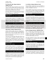
Low DC Bus Voltage (Software) Fault
The low DC Bus voltage trip level is set at 500VDC. If
the DC Bus drops below this level the unit/system will
fault and immediately shut down.
The low DC Bus voltage cutout is an auto-restart safety
that will lock out on the 3rd fault in 90 minutes. The
fault is a unit fault for 2 or 3 compressor units. Below is
an example of the Status display fault message:
UNIT YYYYYYYY
LOW DC BUS VOLTAGE
The low DC Bus voltage cutout is a system fault (1/3
or 2/4) on 4 compressor units. Two key presses of the
STATUS key are required to show the fault on both
systems. Below is a sample Status display system fault
message:
SYS X YYYYYYYY LOW DC BUS VOLTAGE
X indicates the system and YYYYYYY indicates the
system is in a “FAULT” condition and will restart when
the fault clears or “LOCKOUT” and will not restart un-
til the operator clears the fault using the keypad.
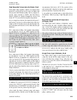
DC Bus Voltage Imbalance (Software) Fault
The 1/2 DC Bus voltage magnitude must remain with-
in plus or minus 100VDC of the total DC Bus voltage
divided by two. If the 1/2 DC Bus magnitude exceeds
the plus or minus 100VDC tolerances, the unit/system
will fault and immediately shut down.
This safety will lock out on the 1st fault. The fault will
be a unit fault for 2 or 3 compressor units. Below is the
Status display fault message:
UNIT YYYYYYYY
DC BUS VOLTAGE IMBALANCE
The fault will be a System 1/3 or 2/4 fault on 4 com-
pressor units. Two key presses of the STATUS key are
required to show the fault on both systems. Below is a
sample Status display fault message:
SYS X YYYYYYYY DC BUS VOLTAGE IMBALANCE
X indicates the system and YYYYYYY indicates the
system is in a “LOCKOUT” condition and will not re-
start until the operator clears the fault using the keypad.
Summary of Contents for YCIV0157
Page 38: ...JOHNSON CONTROLS 38 FORM 201 23 NM2 ISSUE DATE 3 9 2015 THIS PAGE INTENTIONALLY LEFT BLANK ...
Page 42: ...JOHNSON CONTROLS 42 FORM 201 23 NM2 ISSUE DATE 3 9 2015 THIS PAGE INTENTIONALLY LEFT BLANK ...
Page 50: ...JOHNSON CONTROLS 50 FORM 201 23 NM2 ISSUE DATE 3 9 2015 THIS PAGE INTENTIONALLY LEFT BLANK ...
Page 333: ...JOHNSON CONTROLS 333 FORM 201 23 NM2 ISSUE DATE 3 9 2015 NOTES ...

