JOHNSON CONTROLS
27
SECTION 2 - PRODUCT DESCRIPTION
FORM 201.23-NM2
ISSUE DATE: 3/9/2015
2
Oil Cooling
Oil cooling is provided by routing oil from the oil sepa-
rator through several of the top rows of the condenser
coils and back to the compressor.
Capacity Control
When cooling is needed, one or more compressors, as
determined by the system microprocessor based on de-
viation from setpoint, will start at minimum speed with
low inrush current. Variable speed operation of the
compressor reduces the capacity and allows smooth
balancing of the compressor capacity with the cooling
load.
Capacity control is accomplished by varying the num-
ber of compressors and the speed of the compressors
with the VSD to promote stable, smooth, and precise
loading/unloading.
Hot Gas Bypass is not required with VSD control of
the compressors.
The chiller is available with Standard IPLV or High
IPLV software (EPROM). High IPLV software optimiz-
es the performance of the chiller capacity and fan con-
trols. High IPLV chillers also require additional factory
programming.
Power and Control Panel
All controls and the VSD are factory-wired and func-
tion tested. The panel enclosures are designed to
NEMA 3R (IP65) rating and are manufactured from
powder-painted steel with hinged, latched, and gasket
sealed outer doors with wind struts for safer servicing.
The power and micro control panels are combined into
a single control/power cabinet and include:
•
Compressor VSD Controls.
•
Chiller Microprocessor Controls.
•
Fan Controls.
•
All Other Chiller Controls.
The Display and keypad are accessible through an ac-
cess door without opening the main doors to the elec-
trical cabinet.
Each Power Compartment Contains
Incoming single point power is standard utilizing either
a lockable circuit breaker or terminal block, 115VAC
control transformer, VSD, fan contactors, ON/OFF
unit switch, microcomputer keypad and display, Chill-
er Control and VSD Logic Boards, and relay boards.
Current transformers sense each phase of motor cur-
rent, and send corresponding signals to the Chiller
Logic Board. Current monitoring protects the com-
pressor motors from damage due to low motor current,
high motor current, short circuit current, single phas-
ing, and compressor overload.
Short Circuit Withstand Rating of the chiller electrical
enclosure is 30,000 Amps for standard terminal block
connection. Ratings are in accordance with UL508C.
A Circuit Breaker Option can be added to increase the
Short Circuit Withstand Rating to 200/230V equals
100,000 Amps, 380/460 V equals 65,000 Amps, and
575V equals 42,000 Amps.
Microprocessor and VSD Controls
Microprocessors on the Chiller Control Board and
VSD Logic Board control starting, stopping, loading,
unloading, safeties, and chilled liquid temperature
control. Chilled liquid control decisions are a function
of temperature deviation from setpoint and the rate of
change of temperature.
The standard controls include:
•
Brine Chilling.
•
Thermal Storage.
•
Run Signal Contacts.
•
Unit Alarm Contacts.
•
Chilled Liquid Pump Control.
•
Automatic reset after power failure.
•
Automatic system optimization to match operat-
ing conditions.
Remote cycling, optional current limiting, optional
temperature setpoint reset, and optional remote sound
limit can be accomplished by connecting user-supplied
signals to the microprocessor.
Unit operating software is stored in non-volatile mem-
ory. Field programmed setpoints are retained in lithium
battery backed real time clock (RTC) memory for 10
years.
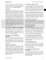
Display
The display consists of a liquid crystal 2 line by 40
characters per line display, with backlighting for out-
door viewing of operating parameters and program
points.
Summary of Contents for YCIV0157
Page 38: ...JOHNSON CONTROLS 38 FORM 201 23 NM2 ISSUE DATE 3 9 2015 THIS PAGE INTENTIONALLY LEFT BLANK ...
Page 42: ...JOHNSON CONTROLS 42 FORM 201 23 NM2 ISSUE DATE 3 9 2015 THIS PAGE INTENTIONALLY LEFT BLANK ...
Page 50: ...JOHNSON CONTROLS 50 FORM 201 23 NM2 ISSUE DATE 3 9 2015 THIS PAGE INTENTIONALLY LEFT BLANK ...
Page 333: ...JOHNSON CONTROLS 333 FORM 201 23 NM2 ISSUE DATE 3 9 2015 NOTES ...

