JOHNSON CONTROLS
297
SECTION 8 - MICROPANEL
FORM 201.23-NM2
ISSUE DATE: 3/9/2015
8
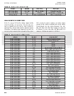
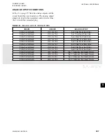
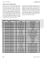
ANALOG OUTPUT CONNECTIONS
lists the analog outputs and the
circuit board they are located on. The analog output
signals are feed to the associated control device from
the 2 wires in the associated plug.
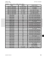
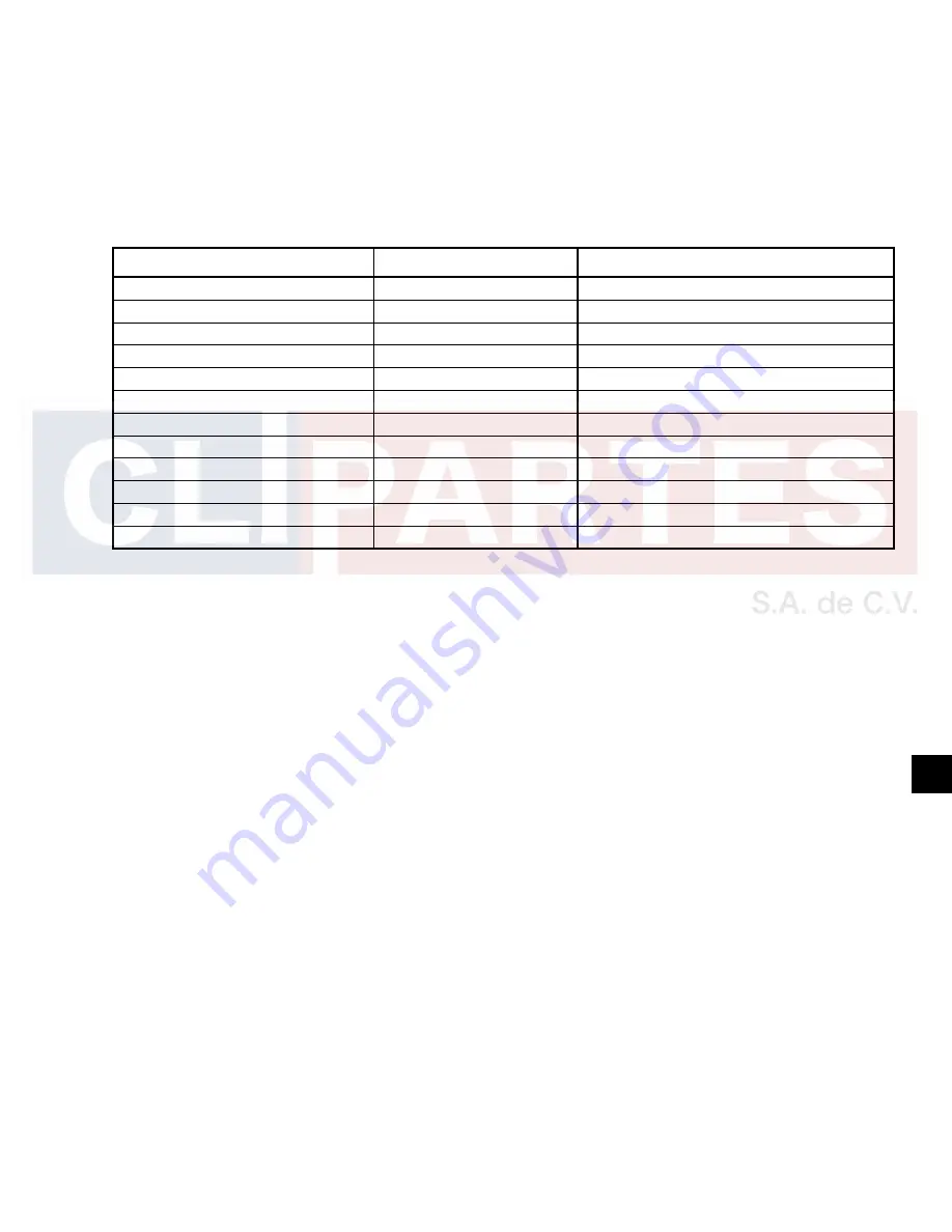
TABLE 23 -
ANALOG OUTPUT CONNECTIONS
BOARD
HEADER
ANALOG OUTPUT
Chiller Control Board
J15-1 to J15-2
Sys 1 Flash Tank Feed Valve
Chiller Control Board
J15-3 to J15-4
Sys 1 Flash tank Drain Valve
Chiller Control Board
J15-5 to J15-6
Sys 2 flash Tank Feed Valve
Chiller Control Board
J15-7 to J15-8
Sys 2 Flash Tank Drain Valve
Chiller Control Board
J14-1 to J14-6
Sys 3 Flash Tank Feed Valve
Chiller Control Board
J14-2 to J14-7
Sys 3 Flash Tank Drain Valve
Chiller Control Board
J14-3 to J14-8
Sys 4 Flash Tank Feed Valve
Chiller Control Board
J14-4 to J14-9
Sys 4 Flash Tank Feed Valve
Chiller Control Board
J25-1 to J25-5
Sys 1 Condenser Fan Speed (Future)
Chiller Control Board
J25-2 to J25-6
Sys 2 Condenser Fan Speed (Future)
Chiller Control Board
J25-3 to J25-7
Sys 3 Condenser Fan Speed (Future)
Chiller Control Board
J25-4 to J25-8
Sys 4 Condenser Fan Speed (Future)
Summary of Contents for YCIV0157
Page 38: ...JOHNSON CONTROLS 38 FORM 201 23 NM2 ISSUE DATE 3 9 2015 THIS PAGE INTENTIONALLY LEFT BLANK ...
Page 42: ...JOHNSON CONTROLS 42 FORM 201 23 NM2 ISSUE DATE 3 9 2015 THIS PAGE INTENTIONALLY LEFT BLANK ...
Page 50: ...JOHNSON CONTROLS 50 FORM 201 23 NM2 ISSUE DATE 3 9 2015 THIS PAGE INTENTIONALLY LEFT BLANK ...
Page 333: ...JOHNSON CONTROLS 333 FORM 201 23 NM2 ISSUE DATE 3 9 2015 NOTES ...

