JOHNSON CONTROLS
56
FORM 201.23-NM2
ISSUE DATE: 3/9/2015
SECTION 5 - COMMISSIONING
JOHNSON CONTROLS
2
FORM 201.23-CL2
ISSUE DATE: 1/12/2015
6.
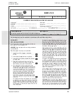
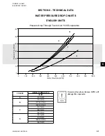
Ensure water pumps are on. Check and adjust
water pump flow rate and pressure drop across
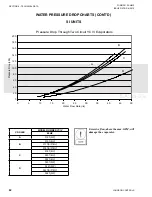
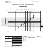
the cooler. ...............................................................
CAUTION:
Excessive flow may cause catastrophic
damage to the evaporator.
7. Check the control panel to ensure it is free of
foreign material (wires, metal chips, tools, docu-
ments, etc.). ............................................................
8. Visually inspect wiring (power and control). Wiring
MUST meet N.E.C. and local codes. ......................
9. Check tightness of the incoming power wiring in-
side the power panel and inside the motor terminal
boxes. .....................................................................
10. Check for proper size fuses in control circuits. .......
11. Verify that field wiring matches the 3-phase
power requirements of the chiller.
(See chiller nameplate) ...........................................
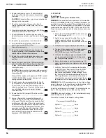
12. Be certain all water temperature sensors are in-
serted completely in their respective wells and are
coated with heat conductive compound. .................
13. Ensure the suction line temperature sensors are
strapped onto the suction lines at 4 or 8 O’clock
positions. .................................................................
14. Assure the glycol level in the VSD cooling system
is 9 to 15 inches (23 to 28 cm) from the top of the
fill tube. This check should be performed prior to
running the pump. ...................................................
CAUTION:
Never run the glycol pump without coolant!
Running the glycol pump without coolant may damage
the pump seals.
Always fill the system with approved YORK coolant
(P/N 013-03344-000) to avoid damage to the pump,
cooling system and the chiller.
15. Check to assure the remote start/stop for Sys #1
on Terminals 2 to 15 and Sys #2 on Terminals 2 to
16 are closed on the User Terminal Block 1TB to
allow the systems to run. If remote cycling devices
are not utilized, place a wire jumper between
these terminals. .......................................................
16.
Ensure that the CLK jumper JP2 on the is in the
ON position. ............................................................
17. Assure a flow switch is connected between Ter-
minals 2 and 13 on the User Terminal Block 1TB
in the panel. Throttle back flow to assure the flow
switch opens with a loss of flow. It is recommend-
ed that auxiliary pump contacts be placed in series
with the flow switch for additional protection, if the
pump is turned off during chiller operation. When-
ever the pump contacts are used, the coil of the
pump starter should be suppressed with an RC
suppressor (031-00808-000). .................................
A. START-UP
Panel Checks
(Power ON – Both System Switches OFF)
WARNING:
You are about to turn power on to this machine.
SAFETY IS NUMBER ONE! Only qualified individuals are
permitted to service this product. The qualified individual fur
-
thermore is to be knowledgeable of, and adhere to, all safe
work practices as required by NEC, OSHA, and NFPA 70E.
Proper personal protection is to be utilized where and when
required.
1. Assure the chiller OFF/ON UNIT switch at the bot-
tom of the keypad is OFF. .......................................
2. Apply 3-phase power to the chiller. Turn on the
optional panel circuit breaker if supplied. The
customer’s disconnection devices can now be set
to ON. ......................................................................
3. Verify the control panel display is illuminated. ........
4. To prevent the compressors from starting, assure
that the system switches under the SYSTEM
SWITCHES key are in the OFF position. ................
5. Verify that the voltage supply corresponds to the
unit requirement and is within the limits given in
the “Technical Data” section. ...................................
6. Ensure the heaters on each compressor are ON
using a clamp-on ammeter. Heater current draw is
approx. 3A. ..............................................................
7. Verify the “Factory Set” overload potentiometers
on the VSD Logic Board are set correctly. Press
the VSD DATA key and using the arrow keys,
scroll to the compressor overload settings. Verify
the “Factory Set” overload potentiometer(s) on the
VSD Logic Board are set correctly. In the unlikely
event that they are not set correctly, adjust the po
-
tentiometers until the desired values are achieved.
WARNING:
The VSD is powered up and live. High voltage
exists in the area of the circuit board on the bus bars, VSD
Pole Assemblies, and wiring to the input inductor.
Adjust the potentiometers, if needed. The potentiometers are
Sys 1=R19, Sys 2=R64, Sys 3=R42, and Sys 4=R86.
CAUTION:
Incorrect settings of the potentiometers may
cause damage to the equipment.
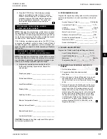
Record the Overload Potentiometer settings below:
Compressor Overload Setting:
System 1 = ______________ Amps
System 2 = ______________ Amps
System 3 = ______________ Amps
System 4 = ______________ Amps
Summary of Contents for YCIV0157
Page 38: ...JOHNSON CONTROLS 38 FORM 201 23 NM2 ISSUE DATE 3 9 2015 THIS PAGE INTENTIONALLY LEFT BLANK ...
Page 42: ...JOHNSON CONTROLS 42 FORM 201 23 NM2 ISSUE DATE 3 9 2015 THIS PAGE INTENTIONALLY LEFT BLANK ...
Page 50: ...JOHNSON CONTROLS 50 FORM 201 23 NM2 ISSUE DATE 3 9 2015 THIS PAGE INTENTIONALLY LEFT BLANK ...
Page 333: ...JOHNSON CONTROLS 333 FORM 201 23 NM2 ISSUE DATE 3 9 2015 NOTES ...


