JOHNSON CONTROLS
218
FORM 201.23-NM2
ISSUE DATE: 3/9/2015
SECTION 7 - OPERATION
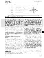
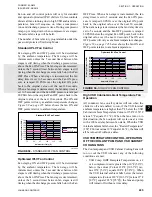
of change of chilled liquid temperature is “positive”
(rising). The Chiller Control Board microprocessor
may also elect to hold capacity when error is “nega-
tive” (temperature is below Setpoint) because the rate
of change of chilled liquid is “positive” (rising).
illustrates these conditions and the re-
sponse from the Chiller Control Board microprocessor.
Hot Water Starts
On a hot water start under “best” case conditions, as-
suming power has not been removed and the 120 sec
timer does not inhibit starting, the design of the con-
trol algorithm for a 2 compressor High IPLV leaving
chilled liquid capacity control allows full loading of a
chiller in slightly more than 6 minutes, regardless of
the number of compressors, if all the compressors start
at the same time. This time period assumes load limit-
ing does not affect the loading sequence and the ambi-
ent is above 40°F.
LOAD LIMITING CONTROL
Load Limiting
The Load Limiting Controls are intended to prevent a
system from reaching a safety trip level. Load limit-
ing controls prevent loading or unload compressors to
prevent tripping on a safety. Limiting controls operate
for Motor Current %FLA, Suction Pressure, Discharge
Pressure, VSD Baseplate Temperature, and VSD Inter-
nal Ambient Temperature.
All running system’s load limit control values are
checked every 2 seconds. Load limiting prevents a
system from loading (no increase even though cooling
demand requires loading) when the specific operating
parameter is within a specific range of values. If the
value is above the range where loading is inhibited, the
logic will unload the chiller based on the amount (%)
the limit has been exceeded. Load limiting affects all
compressors, even though only one system may be af-
fected.
If more than one operating parameter is exceeding
the value where unloading is required, the value with
the highest amount of unloading will determine the
unloading. All load limiting controls are active at start-
up except suction pressure limiting.
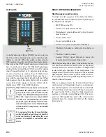
Motor Current Load Limiting/Unloading
Motor current load limiting helps prevent the system
from tripping on the motor overload safety. The motor
“Current Limit Setpoint” is based on %FLA motor cur-
rent and is programmable under the PROGRAM key
or may be set by a remote device. Motor current load
limiting prevents the system from loading even though
increased loading may be required when the current is
between the “Current Limit Setpoint minus 2%” and
the “Current Limit setpoint”. Between the “Current
Limit Setpoint” and the “Current Limit Setpoint plus
5%”, the system will unload every 2 seconds according
to the amount current is exceeding the “Current Limit
Setpoint”. At the “Current limit Setpoint”, 0 Hz reduc-
tion in speed will take place and at the “Current Limit
Setpoint plus 5%”, a 10 Hz speed reduction will take
place. Between the “Current Limit Setpoint” and “Cur-
rent Limit Setpoint plus 5%”, unloading will occur ac-
cording to the
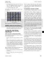
TABLE 6 -
CURRENT LIMIT LOAD LIMITING/
UNLOADING
CURRENT LIMIT SETPOINT
UNLOADING
Current Limit Setpoint -2% to +0%
0 Hz
Current Limit Se1%
2 Hz
Current Limit Se2%
4 Hz
Current Limit Se3%
6 Hz
Current Limit Se4%
8 Hz
Current Limit Se5%
10 Hz
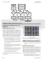
Discharge Pressure Load Limiting/Unloading
Discharge pressure load limiting protects the con-
denser from experiencing dangerously high pressures.
A system is permitted to load normally as long as the
discharge pressure is below the High Discharge Pres-
sure Cutout minus 20 PSIG. Between Cutout minus
20PSIG and Cutout minus 15 PSIG loading is inhib-
ited even though increased loading may be required.
Between Cutout minus 15 PSIG and the Discharge
Pressure Cutout, forced unloading is performed every
2 seconds according to
. The dis-
charge pressure unload point is fixed at 255 PSIG.
Summary of Contents for YCIV0157
Page 38: ...JOHNSON CONTROLS 38 FORM 201 23 NM2 ISSUE DATE 3 9 2015 THIS PAGE INTENTIONALLY LEFT BLANK ...
Page 42: ...JOHNSON CONTROLS 42 FORM 201 23 NM2 ISSUE DATE 3 9 2015 THIS PAGE INTENTIONALLY LEFT BLANK ...
Page 50: ...JOHNSON CONTROLS 50 FORM 201 23 NM2 ISSUE DATE 3 9 2015 THIS PAGE INTENTIONALLY LEFT BLANK ...
Page 333: ...JOHNSON CONTROLS 333 FORM 201 23 NM2 ISSUE DATE 3 9 2015 NOTES ...

