3-11
johNSoN coNtroLS
ForM 102.20-N1 (1109)
3
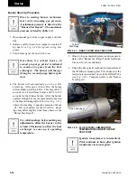
your gas burner has been carefully
inspected and tested at the factory;
however, different conditions at the
jobsite, including controls that have
been added at time of installation,
require careful testing and final ad
-
justment for satisfactory operation.
The Burner Test Report / Factory
Specification Sheet in each unit shows
the general data recorded during the
operation and safety tests at the fac-
tory. This data should be used as a
general guide; with final data recorded
on the start-up form. Do not exceed
550°F flue temperature at the ID fan
inlet. Do not exceed 200°F supply air
temperature.
Introduction
This guideline describes the basic steps a technician
would take in starting an Eclipse Gas Burner 10:1 -
25:1 turndown and Powerflame Gas Burner 3:1 - 10:1
turndown indirect fired gas heat system on a YORK
Solution Air Handler for the first time.
Each gas burner has been test run and inspected at
the factory. Adjustments to component settings are
typically not required. However, measurements of
system parameters should be taken and compared to the
measurements recorded on the “Burner Test Report” to
ensure safe and reliable operation. The “Burner Test
Report” is laminated to the inside of the burner control
door.
Identify the Unit Type
Two types of Indirect Fired gas burners are used on
YORK Solution Air Handlers: The Powerflame series
and the Eclipse series. The Powerflame series offers
a turndown (modulating ratio) of 3:1 or 10:1. The
Powerflame is easily identifiable by the motorized gas
valve with external linkage connecting the air dampers
on the burner air inlet.
The Eclipse series uses an air/gas ratio regulator with
no external linkage, and has a turndown range of 10:1
to 25:1 (sometimes greater). A visible external plastic
tube is used to transmit gas pressure from the burner to
the regulator. No external linkage is used.
Both burners utilize a combustion air blower. YORK
Solution Air Handlers also use an exhaust blower, called
an induced draft (ID) blower. This exhaust blower keeps
the combustion chamber at a slight negative pressure.
Verification of this negative pressure and other system
parameters is part of a proper start up procedure.
indirect Fired gas heat Start up
For your safety and satisfaction, this
product requires check, test and start-
up adjustment by a qualified HVAC
technician. Do not use for temporary
heat prior to start-up.
Review burner control literature, in-
cluding wiring, piping, cut sheets and
drawings before attempting to start
this unit.
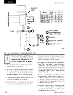
All factory test start up burner speci-
fications are located on a laminated
“Factory Specification Sheet" located
on the inside of the control panel
door”.
Summary of Contents for YORK SOLUTION LD09624
Page 4: ...johnson controls 4 FORM 102 20 N1 1109 THIS PAGE INTENTIONALLY LEFT BLANK ...
Page 10: ...johnson controls 10 FORM 102 20 N1 1109 THIS PAGE INTENTIONALLY LEFT BLANK ...
Page 16: ...johnson controls 16 FORM 102 20 N1 1109 THIS PAGE INTENTIONALLY LEFT BLANK ...
Page 30: ...johnson controls 1 8 FORM 102 20 N1 1109 THIS PAGE INTENTIONALLY LEFT BLANK ...
Page 106: ...johnson controls 2 76 FORM 102 20 N1 1109 THIS PAGE INTENTIONALLY LEFT BLANK ...

