johNSoN coNtroLS
3-14
ForM 102.20-N1 (1109)
Startup
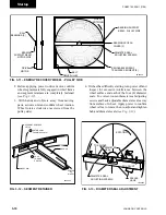
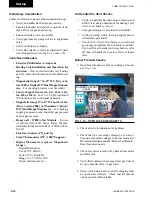
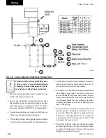
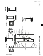
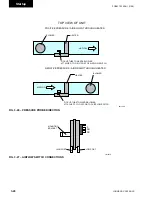
Fig. 3-17 – dRAFt OVER FiRE tESt PORt
5. Observe the gas manifold pressure and compare to
data on the “Burner Test Report” under both High
Fire and Low Fire conditions.
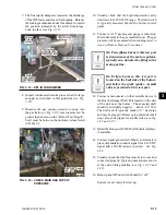
6. Check the flue (stack) combustion temperature at
the ID Blower Housing Test Port. Make sure the
test probe is inserted half way into the ID Inlet Tube
(
see Fig. 3-18).
Compare results to the “Burner
Test Report”.
Fig. 3-18 – FluE (StACK) COMBuStiOn
tEMPERAtuRE And EFFiCiEnCY
tESt PORt
Ignition transformer is intermittent.
Pilot continues to burn after ignition
transformer is de-energized.
Burner Start-Up Procedure
Prior to starting burner, technician
must verify incoming gas pressure.
A minimum pressure is listed on the
“Burner Test Report”. The maximum
pressure is listed in Table 3-2.
1. Open manual gas valves on gas supply and pilot
line.
2. Initiate a call for heat or use jumper to create call
for heat
(see Fig. 3-24 for typical wiring dia-
gram).
3. Turn burner panel off-on switch to on.
Once there is a call for heat, a 30
second pre-purge period is initiated
to remove any gases from the heat
exchanger. The burner will then go
through a second purge before igni-
tion.
4. The burner will automatically go to Low Fire
at start up. After proof of Low Fire, the burner
will modulate up to High Fire. This may take 15
seconds for a Powerflame burner and 90 to 180
seconds for the Eclipse burner. After the burner
operates at High Fire use the manometer connected
to the Heat Exchanger Draft Port
(see Fig. 3-17)
,
observe the reading. A negative pressure of about
-.03
" WC is expected for draft overfire. Read
-
ings may differ slightly from those shown on the
“Burner Test Report”.
For valid readings, before making any
adjustments, allow the burner to fire
at least 20 minutes to allow the heat
exchanger to come up to operating
temperature.
ld12908
tube to
Draft Gage
heat exchanger
draft port
ld12906
iD Fan housing test
port
Summary of Contents for YORK SOLUTION LD09624
Page 4: ...johnson controls 4 FORM 102 20 N1 1109 THIS PAGE INTENTIONALLY LEFT BLANK ...
Page 10: ...johnson controls 10 FORM 102 20 N1 1109 THIS PAGE INTENTIONALLY LEFT BLANK ...
Page 16: ...johnson controls 16 FORM 102 20 N1 1109 THIS PAGE INTENTIONALLY LEFT BLANK ...
Page 30: ...johnson controls 1 8 FORM 102 20 N1 1109 THIS PAGE INTENTIONALLY LEFT BLANK ...
Page 106: ...johnson controls 2 76 FORM 102 20 N1 1109 THIS PAGE INTENTIONALLY LEFT BLANK ...

