3-15
johNSoN coNtroLS
ForM 102.20-N1 (1109)
3
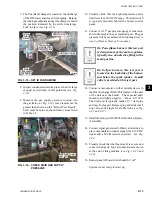
7. Using the signal generator, cycle the burner to
check capacity modulation. Observe valve/damper
actuator operation.
Fig. 3-19 – dAMPER ACtuAtOR
8. Using the standard operating controls, cycle the
burner several times to assure proper sequencing
of start-up, firing, and capacity modulation, plus
operation of all safety and monitoring controls.
9. Test 180°F. high temperature safety by running
burner with airflow off or diverted. Burner
will shut down at 180°F. Turn air handler on as
quickly as possible to remove heat from the heat
exchanger.
10. Burner efficiency testing should be done last. The
burner should be running at High Fire rate for 30
minutes before efficiency testing is done.
11. Efficiency at High Fire is pre-determined, but may
be checked by flue gas analysis at the entrance to
the ID Blower Housing Test Port. At High Fire
CO
2
should be between 8-1/2 and 10 %; 0
2
should
be between 7-1/2 and 4%. With these ranges, effi
-
ciency is 80% plus or minus 2%
(see Fig. 3-18).
12. Contact contractor, facilities manager or customer
to inform successful start-up has been complet-
ed.
In the unlikely event that adjustment
is required; it is done at High Fire and
must NOT retard low Fire light-off.
Do not change set up of factory preset
air inlet dampers on Power Flame
burner.
Any questions should be directed to
your local Service office or Johnson
Controls Product Tech Support, before
contacting the burner manufacturer.
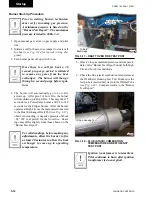
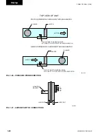
Fig. 3-20 – COndEnSAtE dRAin
Condensate Drain Arrangement
The YORK Solution Indirect Fired gas heat exchanger
has the potential to create highly acidic condensation,
particularly during extended operation at low capacity
or low firing rate conditions. To insure proper drainage
the following guidelines should be followed
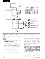
(See Fig.
3-21).
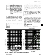
When constructing the condensate trap
for the heat exchanger drainage sys-
tem, make sure the trap is tall enough
to handle the Total Static Pressure of
the ID Blower at low Fire times 2.
Example: TSP is 6” at low Fire -
construct trap 12” tall (See Table in
Fig. 3-21).
LD12911
ld12909
Damper
actuator
marked by factory,
future reference for
actuator set up.
Summary of Contents for YORK SOLUTION LD09624
Page 4: ...johnson controls 4 FORM 102 20 N1 1109 THIS PAGE INTENTIONALLY LEFT BLANK ...
Page 10: ...johnson controls 10 FORM 102 20 N1 1109 THIS PAGE INTENTIONALLY LEFT BLANK ...
Page 16: ...johnson controls 16 FORM 102 20 N1 1109 THIS PAGE INTENTIONALLY LEFT BLANK ...
Page 30: ...johnson controls 1 8 FORM 102 20 N1 1109 THIS PAGE INTENTIONALLY LEFT BLANK ...
Page 106: ...johnson controls 2 76 FORM 102 20 N1 1109 THIS PAGE INTENTIONALLY LEFT BLANK ...

