13
johNSoN coNtroLS
ForM 102.20-N1 (1109)
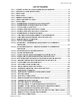
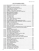
Fig. 2-70 – hOt WAtER PiPing With diVERting VAlVE .................................................................2-47
Fig. 2-71 – StEAM COil PiPing ARRAngEMEntS ............................................................................2-49
Fig. 2-72 – intEgRAl FACE And BYPASS COil (hORiZOntAl; tuBES, StEAM ShOWn) ..........2-50
Fig. 2-73 – VERtiCAl intEgRAl FACE And BYPASS COil ............................................................2-50
Fig. 2-74 – hOt WAtER PiPing FOR 2 ROW COil ViFB ....................................................................2-52
Fig. 2-75 – hOt WAtER PiPing FOR iFB .............................................................................................2-52
Fig. 2-76 – StEAM PiPing FOR ViFB COil ..........................................................................................2-53
FIG. 2-77 – TYPICAL PIPING AND SUNDRIES AT THE DX COIL
.........................................................2-54
FIG. 2-78 – DX COIL CIRCUITING TYPES
.............................................................................................2-55
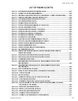
Fig. 2-79 – nOn-StACKEd COil dESign - SQ SPECiAl ...................................................................2-56
Fig. 2-80 – nOn-StACKEd COil dESign - StAndARd .....................................................................2-56
Fig. 2-81 – StACKEd COil dESign - StAndARd ..............................................................................2-57
Fig. 2-82 – StACKEd COil dESignS - SQ SPECiAl ..........................................................................2-57
Fig. 2-83 – StACKEd COil CiRCuiting ..............................................................................................2-57
Fig. 2-84 – OnE COil CiRCuit PERREFRigERAnt CiRCuit ............................................................2-58
Fig. 2-85 – tWO COil CiRCuitS PERREFRigERAnt CiRCuit .........................................................2-58
Fig. 2-86 – dO nOt uSE thE ABOVE COnFiguRAtiOn. ..................................................................2-58
Fig. 2-87 – thREE COMPRESSOR YCul .............................................................................................2-58
Fig. 2-88 – dO nOt uSE thE ABOVE COnFiguRAtiOn. ..................................................................2-58
FIG. 2-89 – SIX COMPRESSOR YCUL
...................................................................................................2-59
Fig. 2-90 – dRAin tRAP ShOWing WAtER lOCAtiOn duRing dRAW thROugh
OPERAtiOn StAgES ..........................................................................................................2-61
Fig. 2-91 – tRAP dEtAil FOR dRAW thROugh APPliCAtiOn .......................................................2-61
Fig. 2-92 – tRAP dEtAil FOR BlOW thROugh APPliCAtiOn .......................................................2-61
Fig. 2-93 – COMBining dRAin linES ..................................................................................................2-62
Fig. 2-94 – RECOMMEndEd diSChARgE duCt ARRAngEMEnt WhEn tuRnS
ARE REQuiREd ....................................................................................................................2-62
Fig. 2-95 – RECOMMEndEd diSChARgE duCt ARRAngEMEnt WhEn tuRnS
ARE REQuiREd ....................................................................................................................2-63
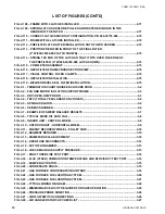
Fig. 2-96 – duCt PEnEtRAtiOn OF ROOF .........................................................................................2-64
Fig. 2-97 – ROOF tO duCt inStAllAtiOn - hORiZOntAl diSChARgE ........................................2-64
Fig. 2-97A – tYPiCAl FiltERS .............................................................................................................2-65
Fig. 2-98 – FiltER lAtChES .................................................................................................................2-66
Fig. 2-99 – CORRECtlY inStAllEd lAtCh P/n 026-35778-000. ......................................................2-68
Fig. 2-100 – FullY inStAllEd FiltER ...............................................................................................2-68
Fig. 2-101 – CORRECtlY inStAllEd lAtCh P/n 026-35778-007 .....................................................2-69
Fig. 2-102 – PlACE thE End OF thE lAtCh OVER thE FiltER FRAME, SECuRing
thE FiltER tO thE FRAME. ............................................................................................2-69
Fig. 2-103 – inStAllEd CARtRidgE FiltER .....................................................................................2-70
Fig. 2-104 – inStAll lAtCh P//n 026-35778-007 ................................................................................2-70
Fig. 2-105 – inStAllEd CARtRigE W/PlEAtS ..................................................................................2-70
Fig. 2-106 – CORRECt uSE OF KnOCKOutS ....................................................................................2-71
Fig. 2-107 – CORRECt lAtCh/KnOCKOut COnFiguRAtiOn. .......................................................2-71
liSt OF FiguRES (COnt'd)
Summary of Contents for YORK SOLUTION LD09624
Page 4: ...johnson controls 4 FORM 102 20 N1 1109 THIS PAGE INTENTIONALLY LEFT BLANK ...
Page 10: ...johnson controls 10 FORM 102 20 N1 1109 THIS PAGE INTENTIONALLY LEFT BLANK ...
Page 16: ...johnson controls 16 FORM 102 20 N1 1109 THIS PAGE INTENTIONALLY LEFT BLANK ...
Page 30: ...johnson controls 1 8 FORM 102 20 N1 1109 THIS PAGE INTENTIONALLY LEFT BLANK ...
Page 106: ...johnson controls 2 76 FORM 102 20 N1 1109 THIS PAGE INTENTIONALLY LEFT BLANK ...


