johNSoN coNtroLS
2-16
ForM 102.20-N1 (1109)
installation
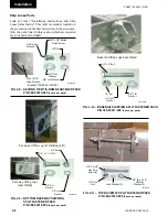
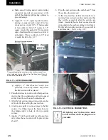
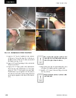
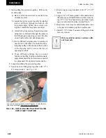
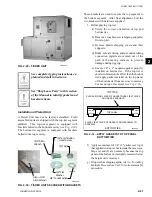
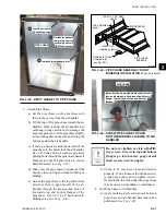
13. Apply a 1/4" bead of caulking to the exterior
of the seam. Trowel the bead level with the air
handler exterior. This is to be done on roof and
both sides
(see Fig. 2-20).
14. Apply 1/4" bead of caulking to the seam inside
the unit on the floor.
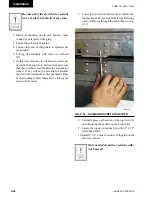
15. Apply 1/4" x 2" foam gasket to the underside of
the seam caps and install them over the joints
using 1/4"-14 x 1" hex head screws provided.
Painted seam caps are applied over the joints on
the sides and roof of the exterior and galvanized
seam caps are applied on the floor of the interior
only.
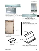
If a roof seam cap has a tab on one
end only, the end without the tab goes
above the pipe chase location.
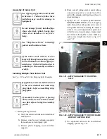
16. Repeat this procedure for each additional section
to be placed in making up the complete unit.
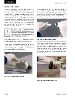
17. Install 1-1/2" Corner Connector Plugs on bottom
raceway corners.
Only needed on units or sections with-
out baserails.
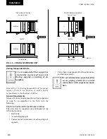
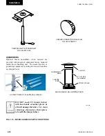
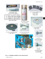
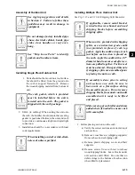
Fig. 2-20
–
BRinging SECtiOnS tOgEthER
LD13775
LD13778
LD13777
LD13776
Summary of Contents for YORK SOLUTION LD09624
Page 4: ...johnson controls 4 FORM 102 20 N1 1109 THIS PAGE INTENTIONALLY LEFT BLANK ...
Page 10: ...johnson controls 10 FORM 102 20 N1 1109 THIS PAGE INTENTIONALLY LEFT BLANK ...
Page 16: ...johnson controls 16 FORM 102 20 N1 1109 THIS PAGE INTENTIONALLY LEFT BLANK ...
Page 30: ...johnson controls 1 8 FORM 102 20 N1 1109 THIS PAGE INTENTIONALLY LEFT BLANK ...
Page 106: ...johnson controls 2 76 FORM 102 20 N1 1109 THIS PAGE INTENTIONALLY LEFT BLANK ...

