johNSoN coNtroLS
2-40
ForM 102.20-N1 (1109)
installation
Available Control Options
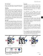
• Staging - No controller, but contactors are
energized by providing control power to each
contactor from external BMS source.
• Step Controller - device to receive a 0- to 10 VDC
or 4 to 20 mA signal and step on heat stages.
• Vernier SCR - completely electronically con
-
trolled by varying signal and varying output
between stages. Increases power to a stage by
modulation until another stage is needed. Ener-
gizes another stage and modulates power until
another stage is needed. 0 to 10 VDC or 4 TO
20 mA. Less expensive than Full SCR. This
system utilizes a step controller and one SCR
that modulates and resets for each stage.
• Full SCR - completely electronically controlled
by varying signal and varying output of a control-
ler. Like a VFD for electric heat. 0 to 10 VDC or
4 to 20 mA. The controller modulates a separate
SCR for each stage.
Installation
Rotating parts and electrical shock
hazards exist. Lock out and tag out
the fan motor(s) and heat power
disconnects before servicing. FOl-
lOW THE lATEST “lOCKOUT
TAGOUT” PROCEDURE. Failure to
follow proper safety precautions may
result in serious injury or death
APPliCAtiOn inFORMAtiOn
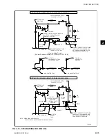
1. Follow the procedure given in this instruction to
find the minimum air velocity for safe operation
(see Fig. 3-25).
At least this minimum velocity
must be provided at all points over the heater face
area. Failure to meet this requirement may result
in serious damage or nuisance thermal cutout trip-
ping.
2. The maximum air inlet temperature for open coil
heaters is 100°F, and for finned tubular heaters,
80°F.
3. Sufficient working space must be provided per
paragraph 110-26 of the NEC.
4. This electric heater is not designed for or intended
to be used for temporary heat prior to system
startup / balancing.
MEChAniCAl inStAllAtiOn
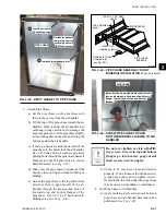
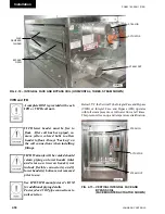
1. All heaters will contain an adjustable airflow
switch in the heater control panel. This switch
will be preset to close at a differential pressure of
approximately 0.3" W.C.
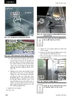
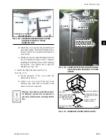
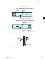
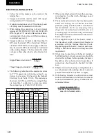
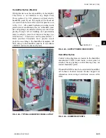
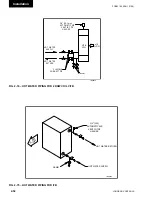
In all cases the switch will be connected to a pres-
sure probe positioned in the airstream. This probe
has an arrow stamped on it that is viewable from
inside of the control panel. When the heater is
located upstream of the fan this arrow will point
away from the fan. When the heater is located on
the downstream side of the fan the arrow will again
point away from the fan or with airflow.
If it is incorrectly installed, remove the (2) screws
holding the pressure probe in place and rotate 180°
and reinstall. The airflow switch pressure port that
is not connected to this pressure probe will be run
to the exterior of the air handling unit to source a
reference differential pressure. In some situations
it may be necessary to adjust this airflow switch
setting to allow for proper operation. Precautions
must be made at this time to make sure that the
airflow switch does not provide a false indication
of airflow. Failure to meet this requirement may
result in serious damage or nuisance thermal cutout
tripping
(see Fig. 2-60 and 2-61).
2. A visual inspection of the heater elements should
be made prior to use of the heater. If physical
damage is evident, a Megohm test should be used
to validate the heater elements are safe for use. If
a minimum value of 10 megohms is not achieved
then any damaged elements or ceramic insulators
must be replaced prior to operation.
Summary of Contents for YORK SOLUTION LD09624
Page 4: ...johnson controls 4 FORM 102 20 N1 1109 THIS PAGE INTENTIONALLY LEFT BLANK ...
Page 10: ...johnson controls 10 FORM 102 20 N1 1109 THIS PAGE INTENTIONALLY LEFT BLANK ...
Page 16: ...johnson controls 16 FORM 102 20 N1 1109 THIS PAGE INTENTIONALLY LEFT BLANK ...
Page 30: ...johnson controls 1 8 FORM 102 20 N1 1109 THIS PAGE INTENTIONALLY LEFT BLANK ...
Page 106: ...johnson controls 2 76 FORM 102 20 N1 1109 THIS PAGE INTENTIONALLY LEFT BLANK ...


