johNSoN coNtroLS
2-46
ForM 102.20-N1 (1109)
installation
Water
Water Coils - hot Water and Chilled Water
Connect the water supply to the header connection on
the leaving air side of the coil to achieve the counter
flow of water and air. The return pipe will be connected
to the remaining coil connection.
Install an air vent in place of the top pipe plug on the
return header. In order to provide for drainage, install
a drain line and shutoff valve in the supply near the coil
or in place of the plug in the supply connection.
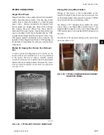
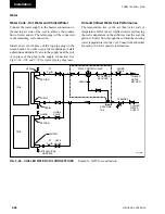
See
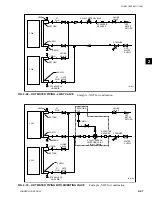
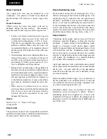
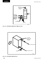
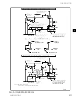
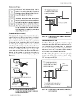
Figs 2-68, 2-69 and 2-70 for typical piping diagrams.
Fig. 2-68 – ChillEd WAtER COil COnnECtiOnS
RETURN
SUPPLY
RETURN
CHILLED
WATER
SUPPLY
REDUCING
TEE
STRAINER
CHILLED
WATER
RETURN
GLOBE
VALVE
GLOBE
VALVE
GATE
VALVE
GATE VALVE W/
HOSE BIB
3 WAY CONTROL VALVE
UNION
UNION
PT
PLUG
PT
PLUG
DRAIN
ECCENTRIC
REDUCER
COIL
VENT
COIL
SUPPLY
LD12939
Example - NOT for construction
hot and Chilled Water Coil Performance
The temperature rise of the air (hot water coil) or
temperature fall of the air (chilled water coil) leaving
the coil is dependent on the airflow across the coil, the
gallons of water flow through the coil and the entering
water temperature into the coil. Consult the submittal
for each job for the specific information.
Summary of Contents for YORK SOLUTION LD09624
Page 4: ...johnson controls 4 FORM 102 20 N1 1109 THIS PAGE INTENTIONALLY LEFT BLANK ...
Page 10: ...johnson controls 10 FORM 102 20 N1 1109 THIS PAGE INTENTIONALLY LEFT BLANK ...
Page 16: ...johnson controls 16 FORM 102 20 N1 1109 THIS PAGE INTENTIONALLY LEFT BLANK ...
Page 30: ...johnson controls 1 8 FORM 102 20 N1 1109 THIS PAGE INTENTIONALLY LEFT BLANK ...
Page 106: ...johnson controls 2 76 FORM 102 20 N1 1109 THIS PAGE INTENTIONALLY LEFT BLANK ...

