2-61
johNSoN coNtroLS
ForM 102.20-N1 (1109)
2
Condensate Drain Trap
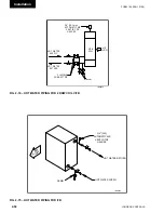
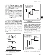
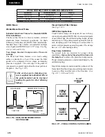
For “Draw Through” applications install a trapped
condensate drain line at unit drain connection (
see Fig.
2-91
) according to all governing codes. “H” dimension
must be at least 1 inch greater than design Total Static
Pressure (TSP) of fan. This ensures proper drainage
even if filters clog or dampers malfunction.
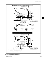
For “Blow Through” applications, the same principles
apply, but the leaving pipe must be as shown in Fig.
2-92 for proper trap design.
"H" must be at least
1 inch plus fan total
static pressure
"X" = 1/2 "H"
H
Fig. 2-91 – tRAP dEtAil FOR dRAW thROugh
APPliCAtiOn
LD05370-2
Fig. 2-92 – tRAP dEtAil FOR BlOW thROugh
APPliCAtiOn
LD05371-2
"H" must be at least
1 inch plus fan total
static pressure
H
Drain
Connection
Top of trap must be equal to or
lower than bottom of unit drain
connection.
drains And traps
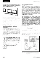
Heat trace and insulate traps where
there is a risk of freezing to prevent
blockage and/or damage due to freez
-
ing of the liquid in the trap.
Auxiliary drain pans may not require
traps. If the trap is not in constant use
the water seal may evaporate causing
air passage into or out of the air han-
dler. In such cases it is recommended
to cap the drain in a manner that al-
lows opening or closing of the drain
depending on its use.
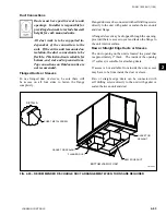
Condensate Drain Piping
The majority of cooling coils are located in the units so
that the supply air is drawn through them. This results
in the condensate being subjected to negative (-) static
pressure. Unless some means of pressure equalization
is provided in the condensate drain, the air rushing
back through the drainpipe will cause the condensate
to build up in the drain pan. As the unit continues to
operate, the accumulated water will be carried with the
air stream, overfilling the drain pan causing possible
water leaks into the supply duct and/or causing water
damage in the building. A trap must be installed to
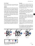
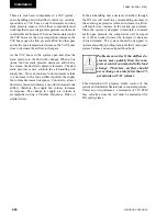
prevent this condensate water build-up (
see Figs 2-90
and 2-91
).
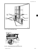
Fig. 2-90 – dRAin tRAP ShOWing WAtER
lOCAtiOn duRing dRAW thROugh
OPERAtiOn StAgES
LD06342-1
DRAIN
PAN
DRAIN
PAN
DRAIN
PAN
DRAIN
NIPPLE
TRAP
NO.1 - FAN OFF
NO. 2 - TRAP CONDITION WHEN FAN STARTS
NO. 3 - FAN RUNNING AND CONDENSATE
COOLING COIL
DRAIN PAN
Summary of Contents for YORK SOLUTION LD09624
Page 4: ...johnson controls 4 FORM 102 20 N1 1109 THIS PAGE INTENTIONALLY LEFT BLANK ...
Page 10: ...johnson controls 10 FORM 102 20 N1 1109 THIS PAGE INTENTIONALLY LEFT BLANK ...
Page 16: ...johnson controls 16 FORM 102 20 N1 1109 THIS PAGE INTENTIONALLY LEFT BLANK ...
Page 30: ...johnson controls 1 8 FORM 102 20 N1 1109 THIS PAGE INTENTIONALLY LEFT BLANK ...
Page 106: ...johnson controls 2 76 FORM 102 20 N1 1109 THIS PAGE INTENTIONALLY LEFT BLANK ...

