2.8.2
YLAA and YLAE 2 Speed Fan Option
The reason for two speed fans it to reduce unit noise by
running the fans in slow speed over as wide a range of
conditions as possible, only going to full speed as a last
resort. This is achieved by raising the pressure at which
the last fan stage occurs, switching from all fans running
in slow speed to all fans running in fast speed.
The Fan On Pressure is programmable under the
PROGRAM key. When the discharge pressure is > Fan
On Pressure and the fan delay timer has expired, the fan
stage is incremented by 1. After incrementing the fan
stage the fan delay timer is set to 5 seconds and the Fan
On Pressure is ramped from 1.4 BARG over the original
value back to the original value over the next 20
seconds. On a fan stage incrementing so that the next
incremented fan stage would result in the fans switching
from slow to fast speed, the fan delay timer is set to 5
seconds and the Fan On Pressure is raised by 5.5
BARG. The Fan OFF Pressure is not move at this time. If
the discharge pressure then rise above this new value
and the fan delay timer has expired, the fan stage is
incremented by 1. The fan delay timer is set to 5
seconds and the Fan OFF Pressure is raised by 5.5
BARG. All fans on full speed.
On a fan stage decrements resulting in the fans
switching from fast to slow speed, the fan delay timer is
set to 5 seconds and the Fan OFF Pressure is lowered
by 5.5 BARG back to the programmed Fan OFF
Pressure. No further lowering or ramping back up,
occurs when this stage decrements. All fans now
running on slow speed. The Fan Off Pressure is equal to
the Fan On Pressure minus the Fan Diff Off Pressure
which is programmable under the PROGRAM key.
On a further fall in discharge pressure when the
discharge pressure is < Fan Off Pressure and the fan
delay timer has expired, the fan stage is decremented
by 1. After decrementing the fan stage the fan delay
timer is set to 5 seconds and the Fan Off Pressure is
ramped from 1.4 BARG below the original value back to
the original value over the next 20 seconds.
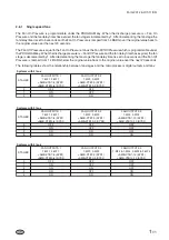
The following tables show the relationship between fan
stages and the microprocessor digital outputs and fans .
2.8.3
Fan Star/Delta Dwell Time
YLAA Units
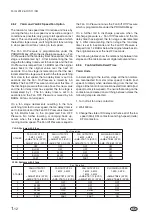
In incrementing to the last fan stage all the fan motors
are reconnected from star (slow speed) to delta (fast
speed). Similarly when decrementing from the last fan
stage all the fan motors are reconnected from delta (fast
speed) to star (slow speed). To ensure that arcing on the
contactors are cleared on switching between states the
following step are enacted.
1. Turn off all fan Line contactors.
2. Wait 500ms.
3. Change the state of KS relay and hence all of the low
speed (Star) KFL contactors and high speed (delta)
KFH contactors.
1
-
12
Form 201.26.OI1(11/09)
YLAA Systems with 3 fans
FAN OUTPUTS 1
1-MF1, 2-MF1
FAN OUTPUTS 2
1-MF2, 2-MF2
FAN OUTPUTS 3
1-MF3, 2-MF3
SLOW/HIGH SPEED
1-KFS, 2-KFS
=AMB-XTB7-8 (SYS1)
=AMB-XTB7-9 (SYS1)
=AMB-XTB7-10 (SYS1)
=AMB-XTB8-5 (SYS1)
=AMB-XTB10-8 (SYS2) =AMB-XTB10-9 (SYS2) =AMB-XTB10-10 (SYS2) =AMB-XTB8-8/9 (SYS2)
0
OFF
OFF
OFF
OFF
1
SLOW
OFF
OFF
OFF
2
SLOW
SLOW
OFF
OFF
3
SLOW
SLOW
SLOW
OFF
4
FAST
FAST
FAST
ON
STAGES
Fan Operation
YLAA Systems with 4 fans
FAN OUTPUTS 1
1-MF1, 2-MF1
FAN OUTPUTS 2
1-MF2, 2-MF2
FAN OUTPUTS 3
1-MF3, 2-MF3
1-MF4, 2-MF4
SLOW/HIGH SPEED
1-KFS, 2-KFS
=AMB-XTB7-8 (SYS1)
=AMB-XTB7-9 (SYS1)
=AMB-XTB7-10 (SYS1)
=AMB-XTB8-5 (SYS1)
=AMB-XTB10-8 (SYS2)
=AMB-XTB10-9 (SYS2)
=AMB-XTB10-10 (SYS2)
=AMB-XTB8-8/9 (SYS2)
0
OFF
OFF
OFF
OFF
1
SLOW
OFF
OFF
OFF
2
SLOW
SLOW
OFF
OFF
3
SLOW
OFF
SLOW
OFF
4
SLOW
SLOW
SLOW
OFF
5
FAST
FAST
FAST
ON
STAGES
Fan Operation


