60
P5417009-rev.6
Communication Cable
Install communication cable while paying attention to the following.
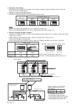
For the combination units, DSW settings of Main and Sub.
● An alarm occurs if the communication cables between main outdoor unit and sub outdoor units are
connected to the terminals 1 and 2 for H-LINK system.
● If an alarm is triggered on the LCD of Main outdoor unit, follow the "7-segment" display at the Main
outdoor unit for verification purposes.
● Perform a function setting at the Main outdoor unit.
● Maximum number of refrigerant groups with one central controller is 64 (for H-LINK II).
Maximum number of indoor units to be connected is 160 (for H-LINK II).
(6) Use the same kind of cables in the same H-LINK system.
(7) Maintain at least 5 inches (127mm) between the communication cables and the power supply wiring,
and also min. 5 ft (1.5m) between the communication cables and power supply wiring for other electrical
device. If these cables are not secured, sleeve the power supply wiring into the metallic conduit tubing
to separate them from the other cables. Make sure power supply wiring are well-grounded.
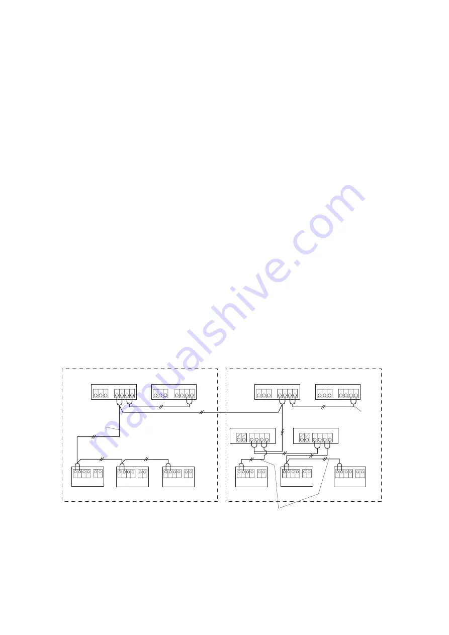
(8) Connect the following communication cables to the terminals 1 and 2 on terminal block (TB2) in the
outdoor unit A (main unit).
• between outdoor unit and indoor unit
• between outdoor unit and change-over box
• between outdoor unit and outdoor unit in other refrigerant systems
(9) Do not connect the power supply wiring to the terminal block for communication cable (TB2).
All the printed circuit boards in the same refrigerant system will be damaged.
(10) For a Heat Recovery System, connect the communication cables from indoor unit exclusively used for
cooling to the terminals 1 and 2 on TB2 in the change-over box.
(11) Connect the ground wiring to the outdoor/indoor units and change-over box. The ground wiring work
under the condition of 100
W
(max.) ground resistance must be performed by a authorized personnel.
(12) Connect the communication cables between outdoor units in the same refrigerant system to the
terminals 3 and 4 on TB2.
Outdoor Unit
(Main)
Outdoor Unit
(Sub)
Outdoor Unit
(Main)
Outdoor Unit
(Sub)
Refrigerant Group 1 (Heat Pump System)
Refrigerant Group 2 (Heat Recovery System)
TB
1
TB
2
TB
1
TB
2
1 2 3 4
L
1
L
2
L
3
1 2 3 4
L
1
L
2
L
3
TB
1
TB
2
B A
2 1
Unit No. 0
TB
1
TB
2
TB
1
TB
2
TB
1
TB
2
TB
1
TB
2
1 2 3 4
1 2 3 4
L
1
L
2
L
3
1 2 3 4
1 2 3 4
L
1
L
2
L
3
Communication Cable
for Main ~ Sub
Change-Over Box No.2
Change-Over Box No.1
Indoor Unit
Indoor Unit
Indoor Unit
Indoor Unit
Indoor Unit
Indoor Unit
Communication Cable
for H-LINK System
Communication Cable for Change-Over Box ~ Indoor Unit
L
2
L
1
TB
1
TB
2
B A
2 1
Unit No. 2
L
2
L
1
TB
1
TB
2
B A
2 1
Unit No. 1
L
2
L
1
TB
1
TB
2
B A
2 1
Unit No. 2
L
2
L
1
TB
1
TB
2
B A
2 1
Unit No. 0
L
2
L
1
TB
1
TB
2
B A
2 1
Unit No. 1
L
2
L
1
L
1
R
L
2
S
L
1
R
L
2
S


