background image


Document Number: SE00458000-00 

Page 16 


3.5.


MOTOR INSTALLATION – LINEAR 
STAGES 

After the Carriage is mounted on the Base the motor can be mounted. SE  motors can be mounted 
on either of the 

motor’s two flat surfaces.  

To install SE motors using the M5 motor thread option, use the following items: 

  Allen wrench 

– M5 for SE8 motor. 

  Screw and washer 

– M5 for  SE8 motors. 

Screw length should be sufficient to pass the base and contact at least 1/  2 the depth of the motor 
body. If the screw protrudes from the motor,  care should be taken that it does not interfere with the 
movement of  other stage parts such as the stroke of the upper axis. 


3.5.1.


MOUNTING SE4 AND SE8 MOTORS ON LINEAR 
STAGE 

Nanomotion  SE4  and  SE8  motors  have  a  preload  screw.  The  motor  is  supplied  with  the  preload 
screw in the locked position and ready for  mounting on the stage. 

1.  Ensure that the preload ex-center is positioned such that the dot on its upper 

surface is farthest from the reference point on the motor case (Figure 9(A)). 

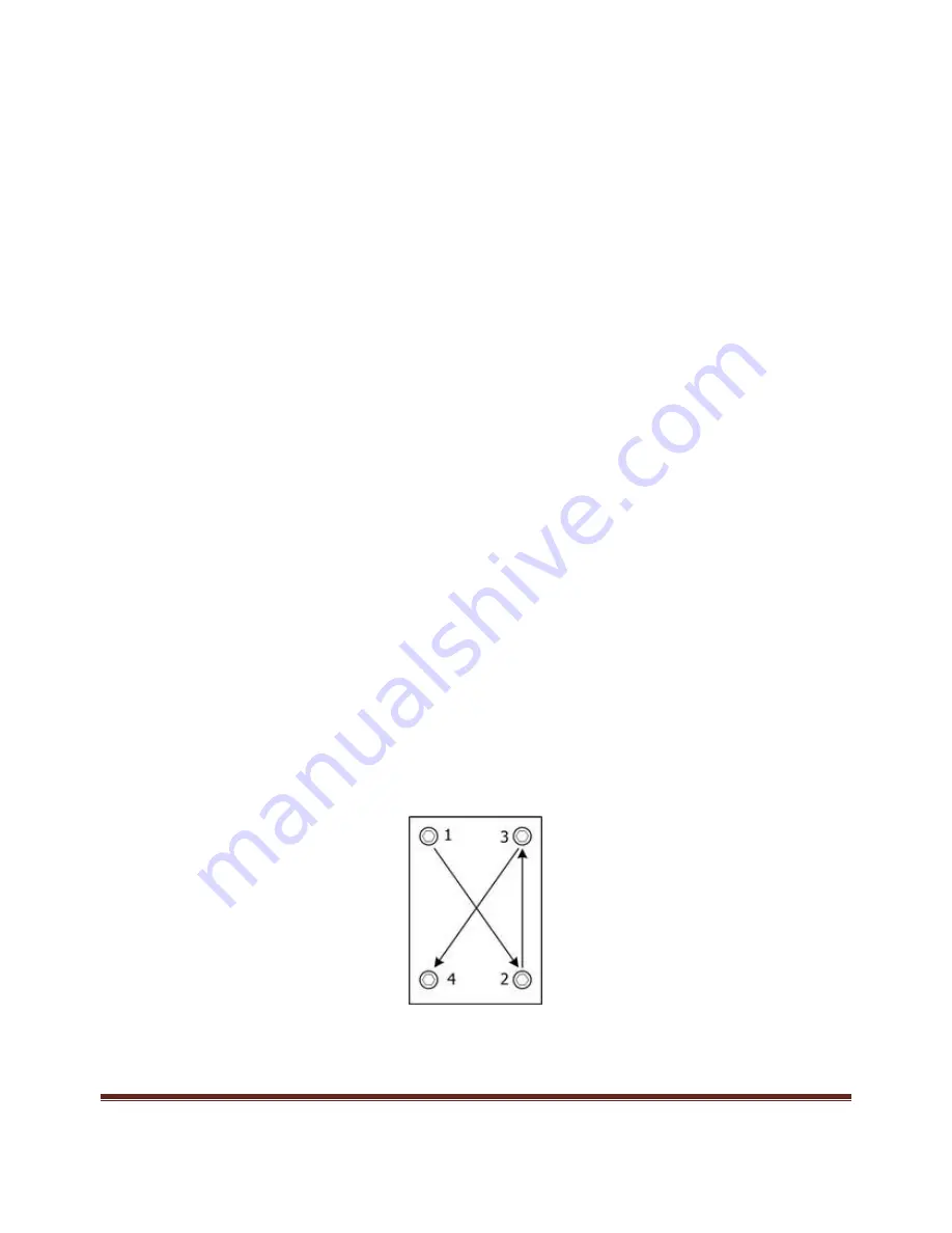
2.  Set the motor in place and finger-tighten the four mounting screws  (M5) and 

washers.  Apply  a  small  amount  of  blue  Loctite  to  the  screws  before 
mounting. 

The motor should be secure but able to move. 

3.  Press the motor so that the motor tips are against the Drive Strip. 

4.  Using  a  diagonal  sequence,  tighten  the  four  mounting  screws  (M5). 

To ensure  that  the  motor  does  not  move  during  this  process  tighten  the 
screws 30% of the required torque first, then tighten them to full torque. 


5.  Apply a torque of 0.5 to 0.7 Nm to each screw. 

6.  Turn the Preload screw CW or CCW until the dot on the screw is closest to 

the reference point on the motor top cover (Figure 9(B)). 

Summary of Contents for Nanomotion SE Series

Page 1: ...age 1 SE Motors User Manual Vacuum Non Vacuum Document No SE00458000 00 Rev B Date December 2020 Nanomotion Ltd POB 623 Yokneam 20692 Israel Tel 972 73 2498000 Fax 972 73 2498099 Web Site www nanomotion com E mail nano nanomotion com ...

Page 2: ...d or applied for patents US 7 439 652 US 7 247 971 US 7 211 929 US 7 199 507 US 7 183 690 US 7 119 477 US 7 075 211 US 7 061 158 US 6 979 936 US 6 879 085 US 6 747 391 US 6 661 153 US 6 617 759 US 6 473 269 US 6 384 515 US 6 367 289 US 6 247 338 US 6 244 076 US 6 064 140 US 5 877 579 US 5 777 423 US 5 714 833 US 5 696 421 US 5 682 076 US 5 640 063 US 5 616 980 US 5 453 653 US 8 514 301 US 8 351 10...

Page 3: ...dwide Headquarters Mordot HaCarmel Industrial Park HaCarmel Street PO Box 623 Yokneam 20692 Tel 972 73 249 8000 Fax 972 73 249 8099 Email nano nanomotion com Nanomotion Inc US Headquarters 1 Comac Loop Suite 14B2 Ronkonkoma NY 11779 Tel 1 800 8216266 Fax 1 631 5851947 Email nanoUS nanomotion com Revision History The revision history shows the last four revisions to this document ECO Revision Relea...

Page 4: ... Bonding the Driving STRIP to the Carriage 14 3 4 1 Mounting Ceramic STRIP on Linear Stage 14 3 5 MOTOR INSTALLATION LINEAR STAGES 16 3 5 1 Mounting SE4 and SE8 motors on Linear Stage 16 3 6 ELECTRICALCONNECTIONS 18 3 6 1 Grounding the Motor 18 3 7 Connecting a Standard Motor Cable 19 4 MOTOR CONDITIONING 21 4 1 Maintenance 22 5 SE MOTOR SPECIFICATIONS AND DIMENSIONS 23 5 1 General Information 23 ...

Page 5: ... 00 Page 5 7 1 VACUUM MOTOR BAKING INSTRUCTIONS 29 7 1 1 Motors Only Procedure 29 7 1 2 Full Systems with Motors Mounted 30 7 1 3 Multiple Motors per Axis Systems 31 7 2 SE4 MECHANICAL DRAWINGS 32 7 3 SE8 MECHANICAL DRAWINGS 33 ...

Page 6: ... is declared EN 50081 2 1993 EN 55011 1991 Generic Emission Standards Class A for radiated emission and Class B for conducted emission EN 50082 2 1995 Generic Immunity Standard 1 2 CONVENTIONS USED IN THIS MANUAL Throughout this manual commands are shown in BOLD and parameter values are shown in italics The following indicate information that is relevant to use and operation of the equipment NOTE ...

Page 7: ...ists Nanomotion products covered by these instructions Product Part Number SE4 Vacuum Motor SE8 Vacuum Motor SE4 1 V 3 SE8 1 V 3 1 4 RELATED DOCUMENTATION The following table lists related Nanomotion guides and manuals Document Document number AB7 Driver User Manual AB07458000 00 ...

Page 8: ...near response to the input voltage Motor Controller Driver SE4 1 V 3 AB7 SE E4 SE8 1 V 3 AB7 SE E8 AB7 SE E16 for 2 motors connected together AB7 SE E32 for 4 motors connected together 2 1 SE MOTOR SYSTEM An SE motor is part of a motion system Figure 1 consisting of the following parts SE Motors SE4 1 V and SE8 1 V motors provided with a 3m shielded cable Ceramic Drive Strip only use ceramic drivi...

Page 9: ...o not apply electric power unless the motor is mounted and pre loaded against a driving strip or a driving ring Do not immerse the motor in any solvent or cleaning agent Use only a clean room cloth to prevent fiber leftovers to wipe the motor case and cover Be sure that the motor and especially the motor s tips are not subjected to mechanical shocks Do not operate Nanomotion vacuum and high vacuum...

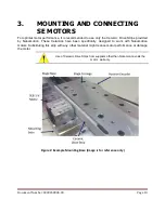
Page 10: ...trips provided by Nanomotion These Ceramics have been specifically designed to work with Nanomotion motors Substituting this strip with any other material might reduce motor performance or damage the motor Use of Ceramic Drive Strips from suppliers other than Nanomotion voids the motor warranty Figure 2 Example Mounting Base image is for reference only ...

Page 11: ...n perpendicular to the motion direction of carriage travel is 50N µm 3 2 MOTOR MOUNTING HOLES The SE4 and SE8 motors have a built in preload setting Therefore the motors are mounted in a fixed position Figure 3 The mounting configuration of SE4 1 V and SE8 1 V motors is shown in Figure 3 All dimensions in this document are in millimeters unless otherwise specified Isometric drawings use European s...

Page 12: ...on of the screws is shown in Figure 3 The ceramic strip must be mounted perpendicular to the mounting base as shown in Figure 2 and Figure 3 The size and position of the ceramic strip should follow the dimensions specified in Figure 4 Figure 5 and Table 1 Figure 4 Position of the Ceramic Drive Strip Table 1 Dimensions from Motor Mounting Base to Drive Strip Motor Type Dimension A Dimension B SE4 1...

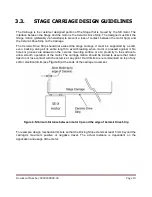
Page 13: ... length to avoid breaking when motor is pressed against it No holes or grooves are allowed on the ceramic mounting surface or at a proximity to the surface to allow smooth operation of the motor The carriage motion should be limited to assure that motor tips do not lose contact with the ceramic at any point Hard limits are recommended on top of any soft or electrical limits see Figure 6 at the end...

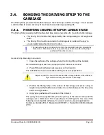
Page 14: ...sed from other sources Ceramic Strip Mounting Instructions 1 Clean the surface of the carriage where the Driving Strip will be bonded Use a suitable agent such as Isopropyl Alcohol Ethanol or Acetone 2 Peel off the self adhesive backing paper on the Ceramic The self adhesive tape is compatible with high vacuum applications Inspect visually to ensure there are no folds or large bubbles in the adhes...

Page 15: ...nd 90 Degree Joints Ensure that the epoxy contacts the ceramic plate and the stage carriage Ensure that it does not flow onto the Ceramic Strip s front surface where motor tips operate 5 Allow the required time period for curing according to the Epoxy manufacturer specifications 6 Mount the Carriage on the Stage 0 ...

Page 16: ... screw The motor is supplied with the preload screw in the locked position and ready for mounting on the stage 1 Ensure that the preload ex center is positioned such that the dot on its upper surface is farthest from the reference point on the motor case Figure 9 A 2 Set the motor in place and finger tighten the four mounting screws M5 and washers Apply a small amount of blue Loctite to the screws...

Page 17: ...Document Number SE00458000 00 Page 17 Figure 9 Preloading of the SE4 and SE8 motors 7 Connect the motor as described in section 3 6 and perform motor conditioning as described in section 4 0 ...

Page 18: ...ble Power and control cable 3 6 1 GROUNDING THE MOTOR Nanomotion motors must be grounded to maintain electrical continuity with the Driver and ensure electrical safety for the system and users The motor is connected to the driver ground via the shield of the motor cable Failure to connect the motor to the system ground is a hazard to personnel safety and equipment operation ...

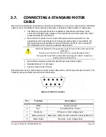
Page 19: ...r to user manual for the installed Driver for maximum allowed cable length The Driver selected for the application must be tuned to the motor used in the application Failure to tune the Driver to the motor may cause damage to Driver Changing the length of the motor cable will change the cable s impedance requiring retuning of the Driver Nanomotion supplies motors with specific low capacitance cabl...

Page 20: ...0 00 Page 20 Pin Function Description 6 Motor Connected Safety input Short pin 6 to pin 1 enables Driver Open on pin 6 disables the Driver 7 GND System ground Connected to connector hood 8 N C Not connected 9 N C Not connected ...

Page 21: ...dure Document number HR00458001 Perform conditioning as follows when using Nanomotion AB7 Driver 1 Set the conditioning procedure to cover the whole expected operated travel of the ceramic drive strip 2 Run the stage repetitively from end to end in closed loop at 0 Horizontal Orientation Perform conditioning only in ambient environment Velocity of 100 mm sec Acceleration 1 5 m sec2 Duty cycle and ...

Page 22: ... plane from time to time The frequency of cleaning depends on the operating environment and type of operating conditions Do not remove the cover of the SE motor The motor has high voltage inside when power is applied To clean the motor tips and ceramic plane 1 Remove power from the motor 2 Turn the turn the pre load screw such that the dot is facing away from the motor tips 3 Loosen the motor moun...

Page 23: ...tandard or linear mode The motor features a linear voltage response The motor and driver can be modeled as a DC motor with friction driven by a voltage amplifier as illustrated in the following diagram Figure 11 Block Diagram of the motor and Driver In the above diagram Vin Command to the driver 10 to 10 V Kf Force constant N V Offset Starting voltage V Kfv Velocity damping factor similar to back ...

Page 24: ...4 Motor SE8 Motor Maximum Attainable Velocity 500 mm sec 500 mm sec Dynamic Stall Force 16 N 32 N Static Holding Force Reference value 14 N 28 N Non Energized Stiffness 4 5 N µm 8 5 N µm Nominal Preload on Stage 60 N 120 N Nominal Lifetime 20 000 hours under nominal operating conditions 20 000 hours under nominal operating conditions Table 3 Electrical Specifications Specification SE4 Motor SE8 Mo...

Page 25: ...fter baking 1e 10 Torr guaranteed only after baking Maximum Baking Temperature for vacuum motors 110º C for standard motors 110º C for standard motors Do not operate Nanomotion vacuum and high vacuum motors in air pressure between 0 1 Torr and 200 Torr Table 5 Physical Dimensions of SE4 and SE8 motors Specification SE4 motor SE8 motor Length 52 29 mm 52 29 mm Width 54 2 mm 54 2 mm Height 14 5 mm 2...

Page 26: ...ted the Driver must be disabled to cool down the motor for 400 sec in air and for 700 sec in vacuum environment The duty cycle is the ratio of the operation time and the total work cycle operation time idle time When operating the motor with the AB7 Driver in linear mode continuously in Brake Off Mode the motor consumes power at all times even when the control command voltage is 0 zero thus the ti...

Page 27: ... driven by an AB7 Driver at the Normal operation mode Curve Air 25 C Air 50 C Vacuum Duty Cycle Maximal Continuous Operation time sec Duty Cycle Maximal Continuous Operation time sec Duty Cycle Maximal Continuous Operation time sec a 100 infinite 100 infinite 100 infinite b 100 infinite 100 infinite 44 184 c 100 infinite 92 137 26 107 d 100 infinite 62 93 17 72 e 78 87 47 70 13 55 f 56 62 33 50 9 ...

Page 28: ...le 6 for the AB7 Driver An example vacuum application requires 15N at a velocity of 100mm sec Figure 13 shows that this point of operation corresponds to the curve d for SE8 motor Table 6 shows that curve d and a vacuum environment require that a duty cycle of 17 will not be exceeded and the maximum continuous operation time is limited to 72 seconds ...

Page 29: ...contaminants and adsorbed humidity from the motors and other system components Nanomotion also supplies ready for use baked motors upon customer s request 7 1 1 MOTORS ONLY PROCEDURE Nanomotion supplies both V and VN motors with a motor connector for initial operation for instance a burn in procedure These connectors are non vacuum compatible Therefore in order to assure optimal motors bake out it...

Page 30: ...g the motor 7 1 2 FULL SYSTEMS WITH MOTORS MOUNTED For baking out a full system with motors mounted perform the following steps 1 Disconnect the motor connector from the driver or the LC box 2 It is assumed that the motor connector is not the NM original connector but rather a custom connector chosen by the stage designer Verify the pinout of the actual connector used in the system and identify th...

Page 31: ... MOTORS PER AXIS SYSTEMS For baking out a system with motors mounted and connected by means of branch cables perform the following steps 1 Disconnect the motors from the branch cable 2 Short circuit the three wire leads of the motor cable white black and red 3 Place the system in a vacuum oven 4 Perform bake ...

Page 32: ...Document Number SE00458000 00 Page 32 7 2 SE4 MECHANICAL DRAWINGS ...

Page 33: ...Document Number SE00458000 00 Page 33 7 3 SE8 MECHANICAL DRAWINGS ...

Reviews: