5
ASSEMBLY INSTRUCTIONS
S6
22#
51# d8*16*1.5 4PCS
50# M8*40*20*S6 4PCS
50
51
50
51
1
7
6
1
4
70
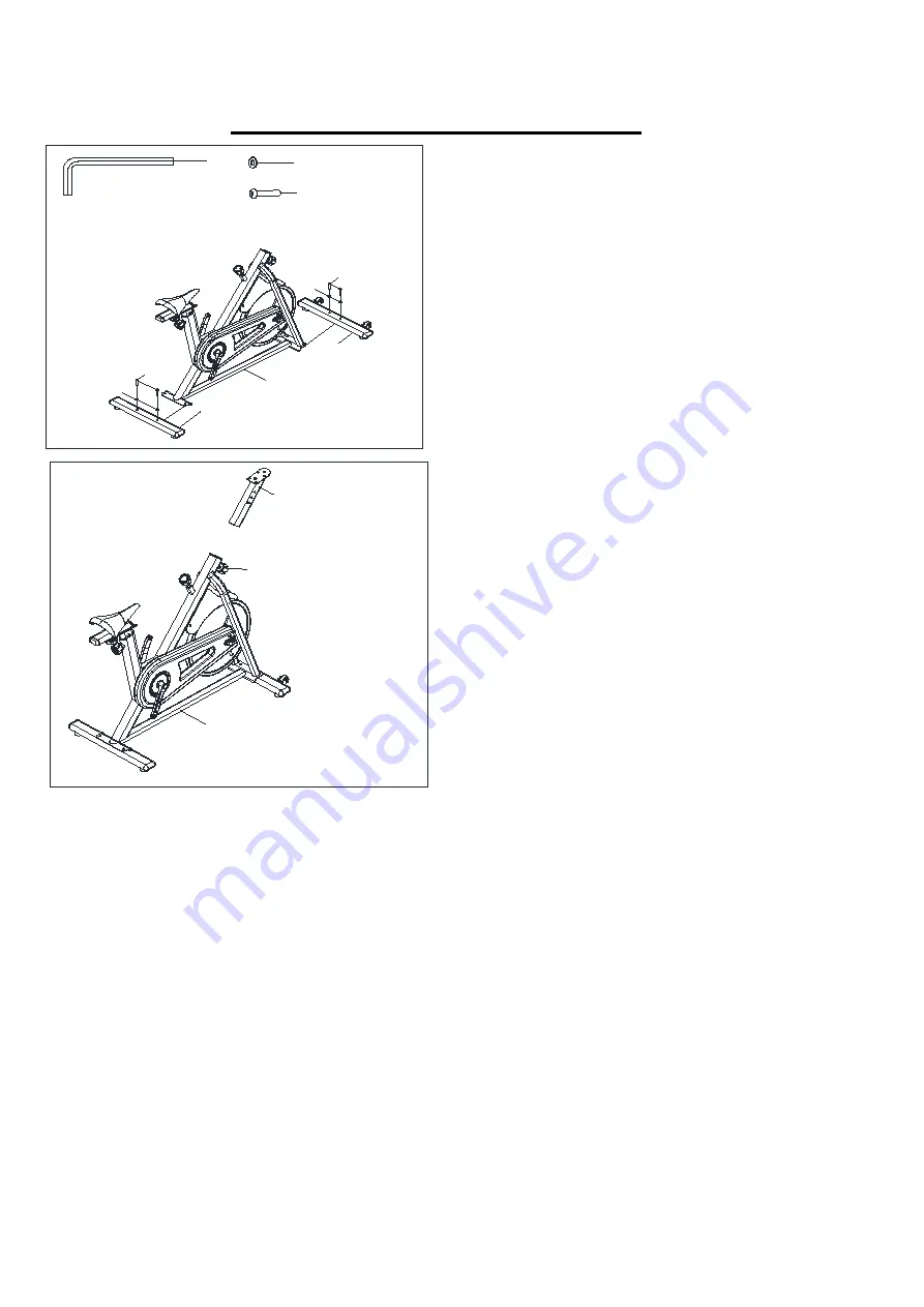
STEP 1:
Attach the
Front
and
Rear Stabilizers (No.6
&
No.7)
to the
Main Frame (No.1)
using 4
Screws
(No.50)
and 4
Flat Washers (No.51)
. Tighten
and secure with
Allen Wrench (No.22)
.
STEP 2 :
Connect the
Spring Wire (No.11)
of the
Handlebar Post (No.4)
with the
Sensor Wire
(No.10)
of the
Main Frame (No.1)
. Loosen and
pull out the
Adjustment Knob (No.70)
. Insert
the
Handlebar Post (No.4)
into the sleeve
located on the front of the
Main Frame (No.1)
.
Adjust the
Handlebar Post (No.4)
to the
desired position, re-insert and tighten the
Adjustment Knob (No.70)
to secure the post
in place.


