background image

                                                                                                                                                                      i-Pilot  rev 04/21 

                                                                                               3 

Case VI.  The i-Pilot GPS-based features drop out when the motor speed setting 
is increased. 

Step 1.

   Suspect a low voltage situation. 

A.


Inspect all battery connections, trolling motor plug (if installed), and any butt splice connections in 
battery leadwire for corrosion and security.  Use of inadequate gauge wire in boat or any leadwire 
extension can result in voltage drop / low voltage to the motor; as can an inadequate or a corroded plug 
/ plug receptacle. 

B.


Ensure the minimum voltage requirements at the motor are met.   


Case VII.  While in Track to Start/End the propeller suddenly stopped.   

Step 1. 

Verify you did not accidentally enable another automatic feature such as AutoPilot or Spot-Lock.  


Step 2. 

The Arrival Mode may be set to OFF.  When the End or Start point of an iTrack is reached the i-Pilot Link will 
automatically cancel iTrack navigation.  Depending on the Arrival Mode chosen, the motor will turn off, go into 
Spot-Lock, or go into AutoPilot.  See i-Pilot Link User Manual for more information. 


Case VIII.  While in Record mode, the recording suddenly stopped. 

Step 1. 

You may have reached the two-mile limit for recording a track. 


Case IX.  When a button on the 1.5 remote is pressed no icons are displayed on 
the remote LCD screen. 

Step 1. 

Use a coin, (a quarter works well), to remove the battery cover on the back side of the remote.  Insert coin in 
slot and rotate the cover about 60° counterclockwise to disengage the cover locking tabs from the case back.  
Turn the remote over and then the cover and CR2450 battery should fall out the back of the remote. 


Step 2.

  Test the remote battery voltage.  A good battery will have at least 2.9 volts.  Replace the battery, if required, and 

reassemble battery and cover into the remote.   

A.


Retest remote for function and icon display.  If no display is noted, replace the remote (p/n 2994170 or 
2994171 for Ulterra).


Case X.  When any button on the 1.0 remote is pressed nothing happens. 

Step 1. 

Open the remote case assembly by removing the six screws on the back side of the remote.   


Step 2. 

Check voltage of the battery in the remote.  A good battery will read at least 2.9 volts.  Replace the battery and 
retest, as necessary. 


NOTE:

  Care must be used when reassembling the remote case.  Be sure to re-install the screws using the same 

threads initially “cut” when the screws were first installed.  The screws should be torqued to about 6 inch-
pounds to ensure proper resealing of the remote assembly. 


Step 3. 

If the battery voltage checked okay, check the security of the battery holder to the remote’s circuit board.  If B+ 
or B- battery connections are loose or if the battery holder is loose from the circuit board replace the remote 
assembly. 


Step 4. 

If the customer reported seeing “moisture” in the LCD window and the remote does not respond to any button 
press then water may have gotten inside the sealed remote enclosure and shorted out the microcircuit on the 
board.  Replace remote assembly. 


Case XI.  When buttons on the 1.0 remote are pressed some of them work and 
others do not, but all buttons “feel” the same. 

Step 1.

   Open the remote case assembly by removing the six screws on the back side of the remote.  Visually inspect the 

dome switches on the front side of the remote circuit board.  If any dome switch is found to be flattened or 
collapsed, replace the remote.  If the dome switches are fine, but a plunger array pin is bent or broken, replace 
the plunger array (p/n 2378451).


©Johnson Outdoors 2021

Summary of Contents for i-Pilot

Page 1: ...l Troubleshooting pages 1 through 6 Part II Miscellaneous System Information pages 7 through 9 Part III Remote Quick Reference Guide pages 10 through 16 Please note the differences in the following pictures as they will be referenced throughout this manual These are referred to as i Pilot remotes Remote for i Pilot 1 0 Remote for i Pilot 1 5 Remote for i Pilot 1 6 p n 2994085 p n 2994170 p n 29941...

Page 2: ... while in AutoPilot Spot Lock or Track to Start End Case II The boat doesn t seem to keep close enough to the recorded Spot Lock location Case III When in Advanced AutoPilot in strong winds there is quite a bit of back and forth movement in the boat Case IV When in Advanced AutoPilot in strong winds there is quite a bit of back and forth movement in the boat Case V i Pilot won t let me turn on cer...

Page 3: ...refer to pictures on first page for remote versions Case XVI The remote LCD backlighting will not come on Case XVII Customer complaint that the battery in the i Pilot remote drains quickly Case XVIII There is moisture in the LCD window or the remote case Case XIX On PowerDrive Riptide PowerDrive models the steering does not work properly or at all following i Pilot installation Case XX The heading...

Page 4: ... is similar and critical for all motors with i Pilot Step 4 The i Pilot GPS based functions are dependent on having good GPS signals Advanced AutoPilot Spot Lock Track to Start End Check to make sure that a good signal is being received and that the GPS signal strength indicator on the i Pilot remote is showing at least one 1 bar See Case V below Step 5 If the motor with i Pilot being serviced is ...

Page 5: ...e I have Advanced selected as the default mode However when I engage AutoPilot it goes into Legacy AutoPilot instead of Advanced Step 1 If the GPS signal strength indicator shows no bars or is flashing then Link will automatically engage Legacy AutoPilot regardless of the Mode selected Wait for your GPS signal strength to reach at least one bar then re engage AutoPilot Case V i Pilot won t let me ...

Page 6: ...d battery will have at least 2 9 volts Replace the battery if required and reassemble battery and cover into the remote A Retest remote for function and icon display If no display is noted replace the remote p n 2994170 or 2994171 for Ulterra Case X When any button on the 1 0 remote is pressed nothing happens Step 1 Open the remote case assembly by removing the six screws on the back side of the r...

Page 7: ...motor functions correctly via foot pedal proceed to Step 3 Step 3 Disconnect Power to the motor A Check the i Pilot coil cord network plug connection in the control box head for corrosion and verify that is fully connected connected properly there should be no yellow visible between the male and female plug ends B Check the network plug s at the Control Board on Terrova Riptide ST motors that have...

Page 8: ... the battery It is simply a warning icon B On early models when a customer wakes up the remote by pressing any button all of the icons were briefly displayed The low battery icon was included in this start up display After the start up display the low battery icon was only shown on the LCD if the voltage in the remote s battery was actually low A software change in later models addressed this by r...

Page 9: ...the remote Observe the voltmeter for voltage A If no voltage is noted when steer left or right button is pressed the i Pilot Controller may be at fault Verify that 12 volts is being provided to the i Pilot Controller by pressing and holding the learn button If a steady tone is heard power is being supplied to the i Pilot Controller but no steering output is present when the steering command is sen...

Page 10: ...e remote ON by pressing and releasing the button Agree to the disclaimer by pressing the Right Softkey If the remote was already ON press the Home button Step 2 Use the Menu Up and Menu Down buttons to find the System menu at the bottom of the display screen NOTE Make sure the remote stays within range of the Control head during the pairing process Step 3 Use the Right Softkey to select the System...

Page 11: ...m a If the system works with the footpedal replace the i Pilot Controller head assembly b If the system does not work with the footpedal review the specific chapter of the repair manual regarding the specific model you are servicing Step 2 While holding the learn button down push any button on the remote being programmed Three short chirps will be heard when the remote is successfully learned AUDI...

Page 12: ...hese enable or disable REC Pause Track to Start Track to End AutoPilot Cruise Control Spot Lock Spot Lock Recall Mode 2 single beep Moving more than a quarter mile from the last track point while in Record Pause mode Mode 2 error When GPS signal strength goes to no bars while in a GPS based mode Mode 2 error Attempting to enable a GPS feature when no signal strength bars are shown Mode 2 error Att...

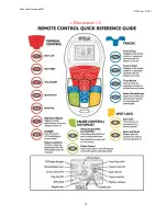
Page 13: ...i Pilot rev 04 21 10 Part III Remote Quick Reference Guide i Pilot remote 1 6 Johnson Outdoors 2021 ...

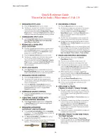
Page 14: ...i Pilot rev 04 21 11 Quick Reference Guide 1 6 Johnson Outdoors 2021 ...

Page 15: ...i Pilot rev 04 21 12 Quick Reference Guide 1 6 Johnson Outdoors 2021 ...

Page 16: ...i Pilot rev 04 21 13 Quick Reference Guide 1 6 Johnson Outdoors 2021 ...

Page 17: ...i Pilot rev 04 21 14 i Pilot remote 1 5 Johnson Outdoors 2021 ...

Page 18: ...i Pilot rev 04 21 15 i Pilot remote 1 0 Johnson Outdoors 2021 ...

Page 19: ...i Pilot rev 04 21 16 Quick Reference Guide This refers to both i Pilot remote 1 5 1 0 Johnson Outdoors 2021 ...

Reviews: