i-Pilot rev 04/21
6
Case XIX. On PowerDrive / Riptide PowerDrive models, the steering does not
work properly or at all following i-Pilot installation.
Step 1.
Verify that the black and white steering motor wires are properly connected to the black and white wires
coming from the i-Pilot Controller cable.
A.
Re-test steering. If steering fails to function, proceed to
Step 2
.
Step 2.
Disconnect black and white steering motor / drive housing leads and connect 12 volts directly to those leads.
A.
If the drive housing does not turn, open the drive housing to inspect the steering motor and drive
housing gears for binding and/or lack of lubrication. Service the drive housing as needed to correct the
malfunction.
B.
If the drive housing does turn, proceed to
Step 3
.
Step 3.
Test output voltage to the steering motor at the black and white i-Pilot Controller cable wires by connecting a
voltmeter to the wires. With proper voltage supplied to the motor send a steering command from the remote.
Observe the voltmeter for voltage.
A.
If no voltage is noted when steer left or right button is pressed, the i-Pilot Controller may be at fault.
Verify that 12 volts is being provided to the i-Pilot Controller by pressing and holding the “learn”
button. If a steady tone is heard, power is being supplied to the i-Pilot Controller, but no steering
output is present when the steering command is sent from the remote. The i-Pilot Controller is at fault
and needs to be replaced.
Case XX. The heading sensor calibration failed. (i-Pilot 1.6 only)
Step 1.
The heading sensor needs to be located in a place where it is not subject to magnetic interference, as it is an
electronic compass. Ensure that the heading sensor is mounted at least 24 inches from magnetic or ferrous
materials or anything that may create a magnetic interference. Some of which may include: base of the
trolling motor, anchors, metal railings, speakers, radios, and trolling motor battery leadwires. It must be
mounted on a flat, horizontal surface with the arrow on the sensor parallel to the boat’s keel. It should have a
line of sight to the i-Pilot Link Controller for best operation.
©Johnson Outdoors 2021
Summary of Contents for i-Pilot
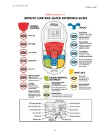
Page 14: ...i Pilot rev 04 21 11 Quick Reference Guide 1 6 Johnson Outdoors 2021 ...
Page 15: ...i Pilot rev 04 21 12 Quick Reference Guide 1 6 Johnson Outdoors 2021 ...
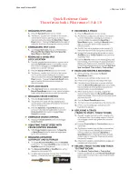
Page 16: ...i Pilot rev 04 21 13 Quick Reference Guide 1 6 Johnson Outdoors 2021 ...
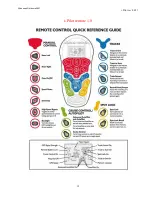
Page 17: ...i Pilot rev 04 21 14 i Pilot remote 1 5 Johnson Outdoors 2021 ...
Page 18: ...i Pilot rev 04 21 15 i Pilot remote 1 0 Johnson Outdoors 2021 ...


