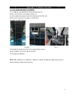
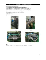
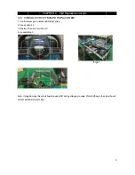
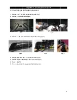
background image

4.6 RUNN

1) Remove 

2) Remove 

3) Remove 

4) Remove 

5) Remove 

6) Reverse

  Note1: 

1.

Adjust

2. The run

belt.

Note:2 

ADJUSTING


After plac

centering. T

cause the b

direction be

Step1: Loca

frame at the

prevent ove

Step2: The 

do not start 

center the b

loosened th

Step3: Whil

Right bolt by

left tighten t

remains cen

Step4: Chec

should not h

necessary.


NING BELT

the motor co

the rear rolle

the running 

the front roll

the running 

e Steps 1-5 t

t running belt

nning deck is

G THE RUN

cing the tread

The belt may 

belt to stretch

elow. 

ate the two h

e back of trea

er tightening 

belt should h

the treadmil

belt by pushin

hem, approxi

e the treadm

y turning it cl

the left bolt b

ntered for se

ck the tensio

hesitate or sl

CHA

T REPLAC

over as outlin

er as outlined

deck as outl

er as outline

belt   

to install a ru

t tension afte

s silicon on o

NING BELT

dmill in the p

need to be a

h at different 

ex head bolt

admill. These

of one side. 

have equal d

l. Turn the b

ng the belt fr

mately one f

mill is running

lockwise 1/4 

by turning it c

everal minute

on of the belt

lip. If this occ

APTER 4:

CEMENT

ned in Sectio

d in Section 4

ined in Secti

ed in Section 

F

unning belt. (

er replaceme

ne side . New

osition it will 

adjusted afte

rates. If the 

t on the rear 

e bolts adjust

istance on e

olts counter 

rom side to s

full turn. Insp

g at 3 mph, o

turns, and lo

lockwise 1/4

es. 

. The belt sh

curs, tighten 

Part Rep

on 4.1. 

4.2. 

on 4.4. 

4.5. 

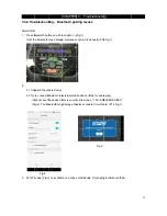
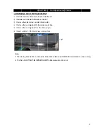
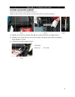
Fig-1           

(Fig-1 & Fig-2

ent (Note2)

w deck surfa

be used, the

er the first 2 h

belt starts to

of the treadm

t the rear roll

either side be

clockwise ap

side. Tighten 

pect the belt f

observe the b

oosen the lef

4 turn and loo

hould be very

the belt by t

placement 

2) 

aces must AL

e belt must b

hours of use

o slip when a 

mill. The bolt

ler. Do not ad

etween the fra

pproximately

the bolts the

for damage.

belt position. 

ft bolt 1/4 turn

osen the righ

y snug. When

urning both b

Guide 

LWAYS be m

be checked fo

. Temperatur

user is on it

ts are located

djust until the

ames. If the b

y one full turn

e same amou

If it is movin

n. If it is mov

t 1/4 turn. Re

n a person w

bolts clockwi

matched to a 

or proper ten

re and humid

, be sure to f

d at each en

e treadmill is

belt is touchi

n on each sid

unt as when 

ng to the righ

ving to the lef

epeat step 3 

walks or run o

ise 1/4 turn, 

29


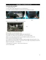
Fig-2 

new running

nsion and 

dity, and use

follow the 

d of the 

s on. This will

ing one side,

de. Manually

the user 

t, tighten the

ft, tighten the

until the belt

on the belt, it

Repeat if 

9

g   


e   

Summary of Contents for AFG Pro 7.2AT

Page 1: ...Rev da Approval le Schweitz ohnso e date 20 vision ate S zer on Ind 016 10 31 AF Serv ustrie Edition Edition ti FG 7 ice M Review es Sh n 01 me 01 7 2A Man w hangh Doc No Page AT nual hai C o Editor A...

Page 2: ...Prod duct Br rowse 2 2...

Page 3: ...o the Console 16 3 3 2 Troubleshooting No Function For Safety Key 17 3 3 3 Troubleshooting No Response for Machine Console Motor 18 3 3 4 Troubleshooting Incline Motor Issues 19 3 3 5 Troubleshooting...

Page 4: ...4 4 7 Motor Control Board MCB Replacement 30 4 8 Incline Motor Replacement 31 4 9 Console Replacement 32 4 10 Console Circuit Board Replacement 33 4 11 Heart Rate Grip and Keypad Replacement 34...

Page 5: ...1 1 Serial SERIAL N l Number NUMBER CHAP Location PTER 1 S Serial Number Locatio on 5 5...

Page 6: ...ncline ndicate wha KNOB rotate g start your w workout Hold st incline in s t speed in sm each desired each desired nd off h speakers w MP3 player i CK plug your nes are plugg power lds personal tablet...

Page 7: ...he inclin uring your wo ts per minute it takes to co at your curre umber of calo simulated tra mile laps on off Note 2 Consol me remaining traveled dur ur walking or ne of your wa orkout e Used to m o...

Page 8: ...3 The J CTRICAL D CN4 MCB JP1 MCB To DIAGRAM B TO Cosole o Inline Pin lo CHAPTER Pin layout ocation R 3 Trou F bleshootin Fig 2 The JP Fig 4 T g P6 Speed se The Voltage ensor to MCB range instr 8 B p...

Page 9: ...CONSOLE E ELECTRIC CAL DIAGR CHAPTER RAM R 3 Troubleshooting 9 9...

Page 10: ...N2 CN3 CN4 CN5 CN6 CIRCUIT B B LED Confi Power Lin Incline mo Speed se Console s Software Drive mot BOARD IN gure ne otor power ca nsor cable set cable burning cabl tor cable CHAPTER NSTRUCTIO able e...

Page 11: ...n lig ght on lig active Fu ght off Dri ght off MC ght off MP MC ght off Inc ght off Inc unction iver Motor ac CB Power ind PU Power In CU status se cline move u cline move d ctive dicator dicator ee T...

Page 12: ...3 2 2 Engineering Mo ode CHAPTER R3 Troub bleshooting g 12 2...

Page 13: ...13 3...

Page 14: ...b To Fro NC Fro Fro To To To To To board Instru LCD display om heart rate om Quick key om Quick key MCB Audio In O Speaker FAN Keypad Blu CHAPTER uctions e grip y Left hand b y right hand b ut interfa...

Page 15: ...1 No sound through the speakers but headphones works 2 No sound through headphones but the speakers work 3 No sound through speakers or headphones 4 IPod not charging 5 Speakers buzzing 6 Sound from...

Page 16: ...l but co F There is a r wer check th ter to measu ltage 110V dard replace check the c CN4 from MC D pin Pin 8 the MCB check the co tions are all g R 3 Trou WER TO TH Fig 1 try another fu onsole doesn...

Page 17: ...tally inserted into the console If not remove and insert again b Check if the safety key is oxidized or its condition does not affect its function If yes try cleaning it or replace it c If the safety...

Page 18: ...and open the motor upper cover Remove the red black wires of motor from the MCB and use a multi meter to measure the resistance of drive motor If the resistance is bigger than 10 the drive motor is d...

Page 19: ...e and scroll to ENG 1 Hardware Test Press the ENTER key first and then the START key c Press the INCLINE key If can hear clicks from two relays at the MCB the MCB is ok Then check the connection of th...

Page 20: ...ers replace if needed 3 Rubbing grinding noise Sol This sound is likely caused by the optic disk Check that the optic disk is tight on the motor and not rubbing the speed sensor 4 Banging or clunking...

Page 21: ...audio adaptor cable connection at the console Replace the headphone jack Replace the audio adaptor cable c There is a bad connection between one of the audio boards and the console Verify the connect...

Page 22: ...ish contact with the HR grip d Replace new HR grip if console can display proper HR rate With a multi meter set for DC voltage place one terminal on each of the HR grip plates The HR Grip should give...

Page 23: ...hers device Bluetooth in e he device na uetooth may 3 no availabl CHAPTER etooth pai ue light on e Replace c external mob ame is your m y damage Re le on phone R 3 Trou iring Issue Fig 1 console circ...

Page 24: ...from y walking belt tor bolts and lt motor towa and motor p uds Fix mo o complete eds HAPTER 4 T he motor cov me So you w 1 otor cover re w motor cove ect after repla LCB speed t off as movi remove mo...

Page 25: ...running n can result i up evenly fro ning are when eet using an NG THE RUN HAPTER 4 CEMENT ear end caps both by altern r belt tension n damage o om the left to n the running abrupt stom NNING BELT 4...

Page 26: ...CH PLACEME d cap Fig 1 back of the tre Fig 1 back of the tre o install a new de rail make not to over t HAPTER 4 NT See section eadmill Fig eadmill w side rail e sure the rea tighten the sc 4 Part Re...

Page 27: ...PLAC cover as outl as outlined in ail as outlined g deck 8 bolt g deck from to install a ne s silicon on o NG THE RUN HAPTER 4 CEMENT lined in Sect n section 4 2 d in Section 4 ts and groun the frame...

Page 28: ...er scr 1 elt from the f roller and mo 1 5mm with equipme g 4 HAPTER 4 CEMENT ned in Sectio rews to remo front roller an otor drive be ent Fig 4 4 Part Re on 4 1 ove tension f nd remove th elt and chec...

Page 29: ...F unning belt er replaceme ne side New T osition it will adjusted afte rates If the t on the rear e bolts adjust istance on e olts counter rom side to s full turn Insp g at 3 mph o turns and lo lockw...

Page 30: ...ps 1 5 to y wire ties re CHA ROL BOAR isconnect the over as outlin connectors a s holding eac o install a new emoved APTER 4 RD MCB e cord from t ned in Sectio at the MCB ch side of the Fig 1 w MCB Ma...

Page 31: ...LA treadmill an over as outlin support it so from the elev Fig 1 e motor from o install a new vation a new incline ts of the incli HAPTER 4 ACEMENT d disconnect ned in Sectio o that the fron vation ra...

Page 32: ...t may c CH PLACEME e treadmill a s holding the s holding the e from the co ole and fasten Fig 1 Fig 3 change the c HAPTER 4 NT and disconne console form console from onsole frame n frame scre console...

Page 33: ...CI wear good co ion 4 9 the new circ step 2 y damage the ar ESD wrist CHAPT RCUIT BO ontact ESD w uit board e circuit boa strap TER 4 Pa OARD REP wrist strap rd cause ES art Replace PLACEMEN D during...

Page 34: ...ypad or e keypad and e step 1 4 n power chec CHA and Keypa s bolts and co grip bars Fig heat rate bar heart rate co d overlay or c the keypad PTER 4 ad replace onnection wi g 2 r and open th onnection...

Reviews: