background image


C7000 Service Manual 


                                                                                                                      Revision:    1.0    Date: 2004/7/25 

Summary of Contents for C7000

Page 1: ...C7000 Service Manual Revision 1 0 Date 2004 7 25 ...

Page 2: ... OF CONTENTS SECTION 1 LIMITED WARRANTY SECTION 2 EXPLODED DIAGRAM SECTION 3 WIRING DIAGRAM SECTION 4 TROUBLE SHLOOTING SECTION 5 PARTS REPLACEMENT SECTION 6 PREVENTIVE MAINTENANCE APPENDIX RECOMMENDED TOOLS ...

Page 3: ...SECTION 1 LIMITED WARRANTY Comments and Questions Scope of Warranty Intended Use Warranty Time Period Defects Replacement Safety Stock of Warranty Parts Defects Return Procedure Technical Support ...

Page 4: ...re warranted against defects in workmanship and materials Any repairs to the parts itself especially the electronics parts will then void the warranty unless the rework is authorized in a written format by JHT in advance This warranty will also not cover any damage failure or loss caused by accident misuse neglect abuse improper assembly or failure to follow instructions or warning in the owner s ...

Page 5: ...rts by express it will be within JHT s discretion how to charge the distributor for both the replacement parts and shipment cost A list of recommended spare parts could be provided with the shipment sales confirmation as long as the request is made to your JHT sales representative and is contained in the service manual as well Please refer to the parts list to fill out the Parts Order Form and sen...

Page 6: ...t It is within JHT s discretion to issue a credit or send parts with no charge to the distributors after the returned parts have been verified to be really defective If the parts returned has been verified to be non defective and is good enough to be used it will be sent back to the distributor The distributor will be responsible for all the shipping cost incurred No credits will be issued on the ...

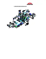
Page 7: ...SECTION 2 EXPLODED DIAGRAM CONTENTS C7000 EXPLODED DIAGRAM ...

Page 8: ...C7000 EXPLODED DIAGRAM ...

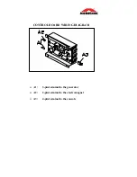
Page 9: ...SECTION 3 WIRING DIAGRAM CONTENTS CONTROL BOARD WIRING DIAGRAM WIRING DIAGRAM ...

Page 10: ...CONTROL BOARD WIRING DIAGRAM A1 3 pin terminal to the generator A2 2 pin terminal to the electromagnet A3 4 pin terminal to the console ...

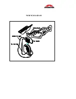
Page 11: ...WIRING DIAGRAM ...

Page 12: ...o RPM is displayed during the exercise ll or some of the function keys do not response Feel the resistance increase decrease or fell no resistance Feel slipping while pedaling nocking or creaking noise o pulse is displayed on console No pulse is displayed on the console hand pulse type Console diagnostics mode N A K N ...

Page 13: ...k if the console cable is connected properly use a multi meter to the VDC If it is replace the console and check again 2 3 Unpl 1 st If it is replace console cable with a new one If it is not next step 4 Unplug the generator cable from the control board and check if the voltage is variable If it is replace the control board with a new one If it is not replace the generator with a new one both inpu...

Page 14: ...ole If it is not connected well Connect the terminal properly If cable is damaged replace it with a new one 2 Console is damaged replace it with a new one 3 Open the side covers of the fitness then replaces the control board with a new one 4 Check if the sensor is misaligned If it is place the sensor in the correct position 5 Open the side covers of the stepper and check if the connection of the s...

Page 15: ...ot fit in properly 2 Keypad is damaged 3 Upper board is damaged Fix 1 Remove the console cover and then check if keypad cable is connected properly to the upper board If it has not been connected well reconnect it to the terminal and check again 2 Keypad or upper board is damaged Replace the console ...

Page 16: ...le cable has been connected properly 2 Console cable is damaged replace it with a new one 3 Remove the side covers of the fitness and check if the terminal of the control board has been connected properly Control board is damaged replace it with a new one 4 Generator is damaged replace with a new one 5 Check if the sensor is positioned correctly Re align the sensor to the correct position 6 Sensor...

Page 17: ...Feel slipping while pedaling Possible causes 1 Belt tension is not enough 2 Poly v Belt is damaged Fix 1 Re adjust the belt tension 2 Replace poly v belt with a new one ...

Page 18: ...nk arm too loose 2 Crank or axle is wear out 3 Belt tension is too loose or poly v belt is too dirty 4 Rail or roller is too dirty Fix 1 Re tighten it 2 Replace it with a new one 3 Re adjust the belt tension and clean the poly v belt 4 Clean the rail and roller ...

Page 19: ...rocedure 1 Place the chest belt in the correct position Remark 1 2 Replace the chest belt with a new one 3 Replace the console with a new one Remark 1 The correct operation of a Chest Belt 1 Moisten the electrodes that are located on both ends of the belt 2 The belt functions will most effective when placed close to the heart and to the skin ...

Page 20: ...ction of hand pulse cable 2 Hand pulse cable is damaged 3 Console is damaged Procedure 1 Remove the console to check if the terminal of hand pulse cable has been connected to PCB well OR 2 Replace the hand pulse cable with a new one OR 3 Replace the console with a new one ...

Page 21: ...B 1 Press the ENTER key 2 Dot Matrix Display will be scanned slowly starting from LEDs at the leftmost column to the right 3 Each 7 segments display will be scanned one by one If one of LEDS is not lit replace the PCB 1 Press the ENTER key 2 Dot Matrix and 7 segments will display lighted up If one of LEDS is not lit replace the PCB 1 Press the ENTER key 2 Dot Matrix Display will show RPM 3 RPM win...

Page 22: ...to increase or decrease resistance If there is no resistance please refer to section 4 4 section 4 5 1 Press the ENTER key 2 Dot Matrix Display will show KEY on it 3 Ready for you to enter any key of all 18 keys other than RESET now to verify the function of the key 4 The RPM window will show you a reference number accordingly while pressing a number or function key 5 TIME window will show you the...

Page 23: ...SECTION 5 SECTION 5 Spare Parts Replacement Spare Parts Replacement Contents Contents GENERAL 5 1 GENERAL 5 1 C7000 C7000 ...

Page 24: ...SECTION 5 1 GENERAL Contents CONSOLE CONSOLE CABLE CONTROL BOARD GENERATOR OR ELECTROMAGNET BRAKE SET ...

Page 25: ...dure 1 Loosen the screws arrow from the console using the screwdriver 2 Disconnect the console cables from the console connectors 3 Replace the console with a new one and reconnect the console cable to the connector 4 Tighten the screws that hold the console to the bracket ...

Page 26: ...sole connectors 3 Remove the upper cover screw 4 Remove the crank and side cover 5 Disconnect the console cable from the connectors and then tie the old cable to the new one with a rigid string 6 Pull the old cable from the top end until the new cable threads all the way through the support 7 Reconnect the console cables to both the console and control board 8 Tighten the screws that hold the cons...

Page 27: ... one 5 Secure the tension screw and the screws holding the generator electromagnet brake set to the frame not too tight at this time so that the tension adjustment can be made 6 Install the POLY V BELT on the front and rear pulley 7 Use the wrench 11mm to adjust the belt tension by adjusting the tension screw until you can only press with your thumb the POLY V BELT down about 1 1 5cm then tighten ...

Page 28: ...SECTION 5 2 Contents CRANK PEDAL POLY V BELT 400 380J6 POLY V BELT 500 440J8 AXLE FRONT PULLEY BALL BEARINGS ...

Page 29: ... 17mm Procedure 1 Loosen the crank cover with a coin and remove it 2 With the crank extractor and open end wrench loosen the screw attaching the crank to 3 Using the crank extractor and open end wrench to extract the crank then replace it with a new one 4 Reverse step 1 3 to install the parts ...

Page 30: ...PEDAL REPLACEMENT PROCEDURE Tools required Open end wrench 15 mm Procedure 1 Using the open end wrench loosen the screws attaching the pedal to the crank 2 Replace the pedal with a new one ...

Page 31: ...de cover with the screwdriver then remove the footpad guard and side cover 2 Loosen the 400 J6 and 500 J8 belts 3 Loosen the screws from the front pulley by using the hex key 4mm then remove the front pulley 4 Replace the 400 380 J6 belt with a new one 5 Tighten the screws from the front pulley by using the hex key 4mm 6 front and rear pulleys 7 and the parts Install 400 380 J6 and 500 440 J8 belt...

Page 32: ... Tools required Philips screwdriver Hex key 4mm Open end wrench 14mm Crank Open end wrench Procedure Remove the crank cover and screw then rem the crank Refer to section 5 2 1 Loosen the screws from cover with the screw Loosen the screws from the front pulley by using the hex key 4mm and the fit in screw o spring by using screwdriver The spring replacement is danger Take special cautions during th...

Page 33: ...0 440J8 400 380J6 3 With the C Clip Pliers Replace the axle with a new one then install the c clip by using c clip pliers Reverse the step 1 3 to install the parts Philips hammer Coin Crank extractor Hex key 4mm ocedure Remove the crank cov and screw then remove the crank Loose cover with the screwdriver th side covers 2 from the axle remove the C clip 4 With the wooden hammer tap the axle out 5 6...

Page 34: ...and screw then remove the crank Loosen the screws from the side cover with the screwdr o side cover Loosen the screw A and remove it for th axle pulley assembly of the new design Remove the spring attaching the idler pulley to th frame first then loosen the screws attaching the bearing housing to the axle pulley assembly usi the hex key 4mm The spring replacement dangerous Take special cautions du...

Page 35: ...by using the c clip pliers and remove the metal pulley from the generator using the Bearing Puller 6 Remove the c clip D by using the c clip pliers and remove the idler using the Bearing Puller 7 Remove the c clip B by using the c clip pliers and remove the Bearing Housing using the Bearing Puller 8 Replace the axle pulley assembly with a new one 9 Reverse step 1 9 to install the parts ...

Page 36: ...the side cover with the screwdriver then remo footpad guard and side ve cover 2 6 tion so you will not damage both 3 n screws holding the bearing housing to the 4 Clip Pliers remove the C clip and then earing Housing If the Ball Bearing failed replace it Loosen the POLY V belts 500 440J8 400 380J and the fit in screw of idler spring The spring replacement is dangerous Take special cautions during ...

Page 37: ...nk extractor rocedure 5 s y e Bearing lace pulley assembly 6 e Replace bearing with a Open end wren 14 17 mm P Remove the C clip c with the C Clip Plier and then remove the pulley Assembly b using th Puller If the Ball Bearing failed rep Remove the C clip D with the C Clip Pliers and then remove th idler Assembly by using the Bearing Puller then strike bearing out from the housing of 7 ...

Page 38: ...SECTION 6 MAINTENANCE PROCEDURE CONTENTS CLEANING THE GROOVES ...

Page 39: ...and pulleys noises will be generated during operation Procedure 1 Remove the Poly V belts and check the grooves of the belt for dirt or dust and clean it if any 2 Check the grooves in the pulley for dirt or dust and clean it if any 3 Check the grooves in the roller pulley for dirt or dust and clean it if any ...

Page 40: ...OMMENDED TOOLS A OPEN END WRENCH 17mm B OPEN END WRENCH 14mm A B C D E F G C RATCHET BOX WRENCH 11mm D PHILIPS SCREWDRIVER E SLOTTED SCREWDRIVER F CRANK EXTRACTOR G MULTIMETER HEX KEYS 1 5 2 2 5 3 4 5 5 5 6 8 10 mm ...

Page 41: ...APPENDIX 1 WOODEN HAMMER 2 BEARING PULLER 3 C CLIP PLIERS 4 C CLIP PLIERS 1 2 3 4 ...

Reviews: