


Console Diagnostics Mode
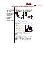
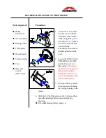
STEP 1
STEP 2
STEP 3
STEP 4
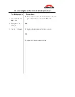
1.
Sit
(stand)
on your bike
(stepper
), Press and hold
down the "RESET” key then
(for stepper turn
the power on)
start pedaling to reach a pedal
speed of approximately 30rpm.
OR
Press and
hold down the "RESET” key then plug the
adapter (JPE).
2.
Dot Matrix Display will be scanned slowly starting
from LEDs of the bottom row to the top; each
segment of the 7-segments will be scanned
simultaneously
If one of LEDS is not lit, replace the PCB.
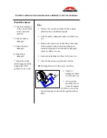
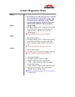
1.
Press the ENTER key.
2.
Dot Matrix Display will be scanned slowly starting
from LEDs at the leftmost column to the right.
3.
Each 7-segments display will be scanned one by
one.
If one of LEDS is not lit, replace the PCB.
1.
Press the ENTER key.
2.
Dot Matrix and 7-segments will display lighted up
If one of LEDS is not lit, replace the PCB.
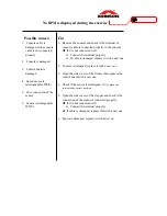
1.
Press the ENTER key.
2.
Dot Matrix Display will show “RPM”.
3.
“RPM” window will show current RPM
4.
“TIME” window will show total accumulated
minutes and seconds.
5.
“AGE” window will show total accumulated hour.
6.
Hold down the ”RESET” key first then press
“PAUSE” key to clear the record.
If RPM is not shown, please refer to section 4-2 for
troubleshooting.
Summary of Contents for C7000
Page 1: ...C7000 Service Manual Revision 1 0 Date 2004 7 25 ...
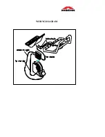
Page 7: ...SECTION 2 EXPLODED DIAGRAM CONTENTS C7000 EXPLODED DIAGRAM ...
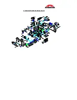
Page 8: ...C7000 EXPLODED DIAGRAM ...
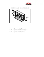
Page 9: ...SECTION 3 WIRING DIAGRAM CONTENTS CONTROL BOARD WIRING DIAGRAM WIRING DIAGRAM ...
Page 11: ...WIRING DIAGRAM ...
Page 38: ...SECTION 6 MAINTENANCE PROCEDURE CONTENTS CLEANING THE GROOVES ...
Page 41: ...APPENDIX 1 WOODEN HAMMER 2 BEARING PULLER 3 C CLIP PLIERS 4 C CLIP PLIERS 1 2 3 4 ...


