
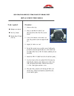
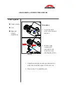


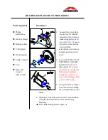

idler assembly.
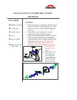
new one.
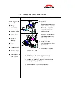
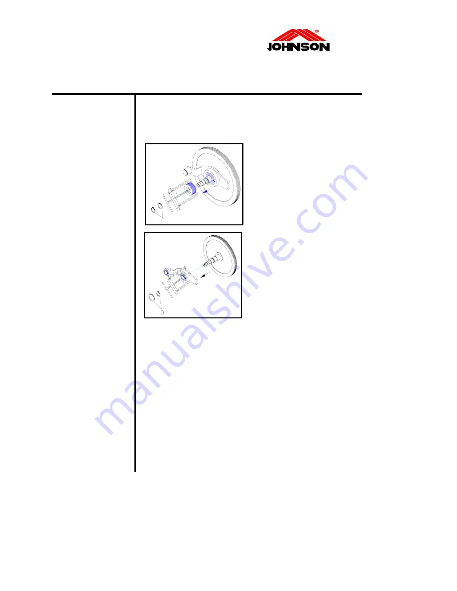
Reverse step 1-7 to install the parts.
BEARING REPLACEMENT PROCEDURE
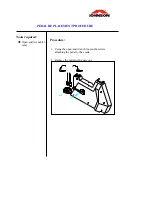
Tools required:
Philips screwdriver
Hex key (4mm)
Bearing puller
C-Clip pliers
Wooden hammer
ch
Crank extractor
rocedure:
5.
s
y
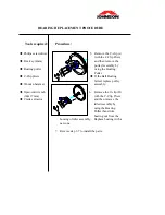
e Bearing
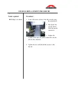
lace pulley
assembly.
6.
e
Replace bearing with a
.
Open-end wren
(14&17 mm)
P
Remove the C-clip (c)
with the C-Clip Plier
and then remove the
pulley Assembly b
using th
Puller.
If the Ball Bearing
failed, rep
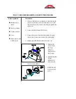
Remove the C-clip (D)
with the C-Clip Pliers
and then remove th
idler Assembly by
using the Bearing
Puller then strike
bearing out from the
housing of
7
Summary of Contents for C7000
Page 1: ...C7000 Service Manual Revision 1 0 Date 2004 7 25 ...
Page 7: ...SECTION 2 EXPLODED DIAGRAM CONTENTS C7000 EXPLODED DIAGRAM ...
Page 8: ...C7000 EXPLODED DIAGRAM ...
Page 9: ...SECTION 3 WIRING DIAGRAM CONTENTS CONTROL BOARD WIRING DIAGRAM WIRING DIAGRAM ...
Page 11: ...WIRING DIAGRAM ...
Page 38: ...SECTION 6 MAINTENANCE PROCEDURE CONTENTS CLEANING THE GROOVES ...
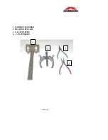
Page 41: ...APPENDIX 1 WOODEN HAMMER 2 BEARING PULLER 3 C CLIP PLIERS 4 C CLIP PLIERS 1 2 3 4 ...


