background image

1

Johnson  C8000 

SERVICE MANUAL

Summary of Contents for C8000

Page 1: ...1 Johnson C8000 SERVICE MANUAL ...

Page 2: ...enerator Wire wiring diagram 10 SECTION 3 CONSOLE ENGINEERING MODE GUIDE 11 1 How to enter into the engineering mode 12 15 SECTION 4 TROUBLESHLOOTING 16 1 No display on the console or the display is dim 17 2 All or some of the function keys do not respond 18 3 No resistance change or too hard for pedaling 19 4 Feel slipping while pedaling 20 5 Knocking or creaking noises 20 6 Heart Rate Control fu...

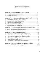
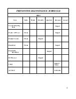
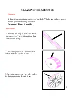
Page 3: ...3 SECTION 1 MAINTENANCE PROCEDURE ...

Page 4: ...pect Belt Grooves Inspect Handrail Handlebar Inspect Clean Handlebar Inspect Clean Display Console Inspect Clean Frame All Cover Inspect Console Mounting Bolts Annual Biannual Quarterly Monthly Weekly Daily Item BIKE PREVENTIVE MAINTENANCE SCHEDULE ...

Page 5: ...operation Frequency Every 6 months CLEANING THE GROOVES Procedure 1 Remove the Poly V belts and check the grooves of the belt for dirt or dust and clean it if any 2 Check the grooves in the pulley for dirt or dust and clean it if any 3 Check the grooves in the roller pulley for dirt or dust and clean it if any ...

Page 6: ...6 SECTION 2 WIRING DIAGRAM INSTRUCTION ...

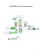
Page 7: ...7 C8000 CB66 Electrical block diagram ...

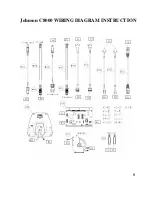
Page 8: ...8 Johnson C8000 WIRING DIAGRAM INSTRUCTION ...

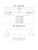
Page 9: ...9 P01 Console cable P02 Pulse sensor wire ...

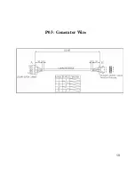
Page 10: ...10 P03 Generator Wire ...

Page 11: ...11 SECTION 3 CONSOLE ENGINEERING MODE GUIDE ...

Page 12: ...ing use the LEFT RIGHT ARROW keys or LEVEL ARROW keys 4 To confirm and save the value of the setting press the QUICK START key SETTING SAVED will appear in the INSTRUCTION CENTER To exit the setting without saving press the RESET key within 5 seconds or if there is no key pressed the system will resume automatically 1 To enter the Manager s Custom Mode press and hold down the LEVEL UP and DOWN arr...

Page 13: ...13 ...

Page 14: ...14 ...

Page 15: ...15 ...

Page 16: ...16 SECTION 4 TROUBLESHOOTINGS ...

Page 17: ...se a multi meter to check if the voltage between the 1 Vcc and 7 Ground pin of the console cable is greater than 12 If it is replace the console and check again 2 Open the side covers then check if all the wire harnesses are connected properly to the terminals of the control board 3 Unplug the generator cable from the Controller and pedal the machine to check if the voltage is variable If it is re...

Page 18: ... not fit in properly 2 Keypad is damaged 3 Upper board is damaged Fix 1 Remove the console cover and then check if keypad cable is connected properly to the upper board If it has not been connected well reconnect it to the terminal and check again 2 Keypad or upper board is damaged Replace the console ...

Page 19: ... is damaged 4 Controller is damaged Fix 1 Remove the console and check if the console cable has been connected properly 2 Remove the side covers and check if the console cable is connected well to the controller properly 3 Please make use of tools to confirm Generator have conduct 10 15Ω If it is damage Please replace Generator If it is well Please replace control board ...

Page 20: ...elt tension is correctly 3 One way bearing is damaged Replace it with a new one instruction see below Knocking or creaking noises Possible causes 1 Pedal is on crank arm too loose 2 Crank or axle is wear out 3 Belt tension is too loose or poly v belt is too dirty Fix 1 Re tighten it 2 Replace it with a new one 3 Re adjust the belt tension and clean the poly v belt ...

Page 21: ...d 5 PCB is damaged Fix 1 Center the bike on your chest below the pectoral muscle breast as shown then check again 2 Remove the battery cover of the bike Replace a new battery and check again Actually as moisture may activate the transmitter please dry transmitter after use 3 Transmitter is damaged Replace the Transmitter 4 Heart rate control board is damaged Replace the HR control board 5 PCB is d...

Page 22: ...22 SECTION 5 SOFTWARE UPGRADE PROCEDURE ...

Page 23: ...23 Johnson C7000 BIKE SOFTWARE UPGRADE SOP A Service Tools Accessories 1 MSP FET430 Please refer the bulletin NB 0506002 2 Parts NO MT00L 039 3 Software ...

Page 24: ...ameter Press the File Name Find out the software version file in the computer and then actuate open the file 1 2 4 3 5 6 Note When upgrade LCB the device type 3 has to select MSP430 F135 When upgrade PCB the device type 3 has to select MSP430 F149 ...

Page 25: ...25 Install the MSP430 Tools Computer ...

Page 26: ...26 Press the Load Image Installation software to MSP430 Tools ...

Page 27: ...27 Installing the MSP430 cable to console MSP430 ...

Page 28: ... key the MODE light will to glitter about 10 sec If installing pass the OK LET light 2 Drive the machine to provide power for console and then enter into the engineering mode to confirm if the software had been installed upgraded ...

Reviews: