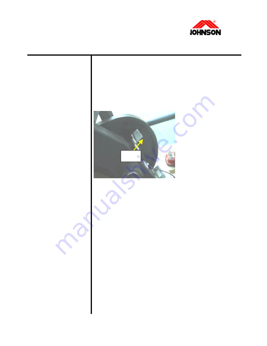
SENSOR REPLACEMENT PROCEDURE
(JPE5100)
Tools required: Procedure:
u
Philips screwdriver
u
Hex key (5mm)
u
Ratchet Box Wrench
(11mm)
1.
Remove the rear cover.
2.
Disconnect the sensor cable from the control board.
3.
Loosen the screws that hold the sensor to the frame.
4.
Replace the sensor
with a new one.
5.
Reverse the step 1-3
to install the parts.
Sensor
3-25 Revision: 1.0 Date: 2001/06/01
Summary of Contents for JAR-5100
Page 1: ...o JPB 5100 o JPS 5100 o JAR 6000 o JPC 5100 o JPE 5100 o JAR 5100 ...
Page 5: ...SECTION 1 WIRING DIAGRAM Revision 1 0 Date 2001 06 01 ...
Page 11: ...JPC B 5100 WIRING DIAGRAM 1 6 Revision 1 0 Date 2001 06 01 ...
Page 12: ...JPS 5100 WIRING DIAGRAM 1 7 Revision 1 0 Date 2001 06 01 ...
Page 13: ...JAR 5100 WIRING DIAGRAM 1 8 Revision 1 0 Date 2001 06 01 ...
Page 14: ...JPE 5100 WIRING DIAGRAM 1 9 Revision 1 0 Date 2001 06 01 ...
Page 35: ...SECTION 3 PARTS REPLACEMENT PROCEDURE Revision 1 0 Date 2001 06 01 ...
Page 72: ...SECTION 4 PREMENTIVE MAINTENANCE Revision 1 0 Date 2001 06 01 ...
Page 76: ...SECTION 5 SERVICE FORM Revision 1 0 Date 2001 06 01 ...


