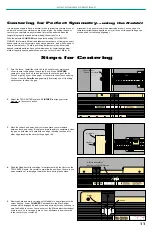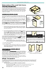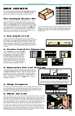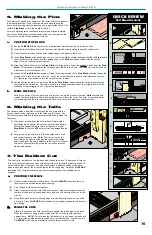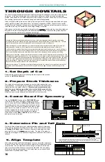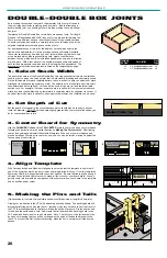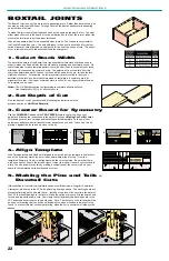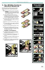
JOINT MAKING OPERATIONS
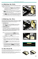
7. Making the Pins
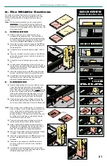
Pins are normally made by passing the workpiece horizontally into the bit. The Jointech
Through Dovetail employs both a horizontal (sliding) cut and a vertical cut to make the
pin. Both operations are made with the same bit at the same height setting. Use the
assigned template lines for pins to make both cuts to the pin boards.
a.
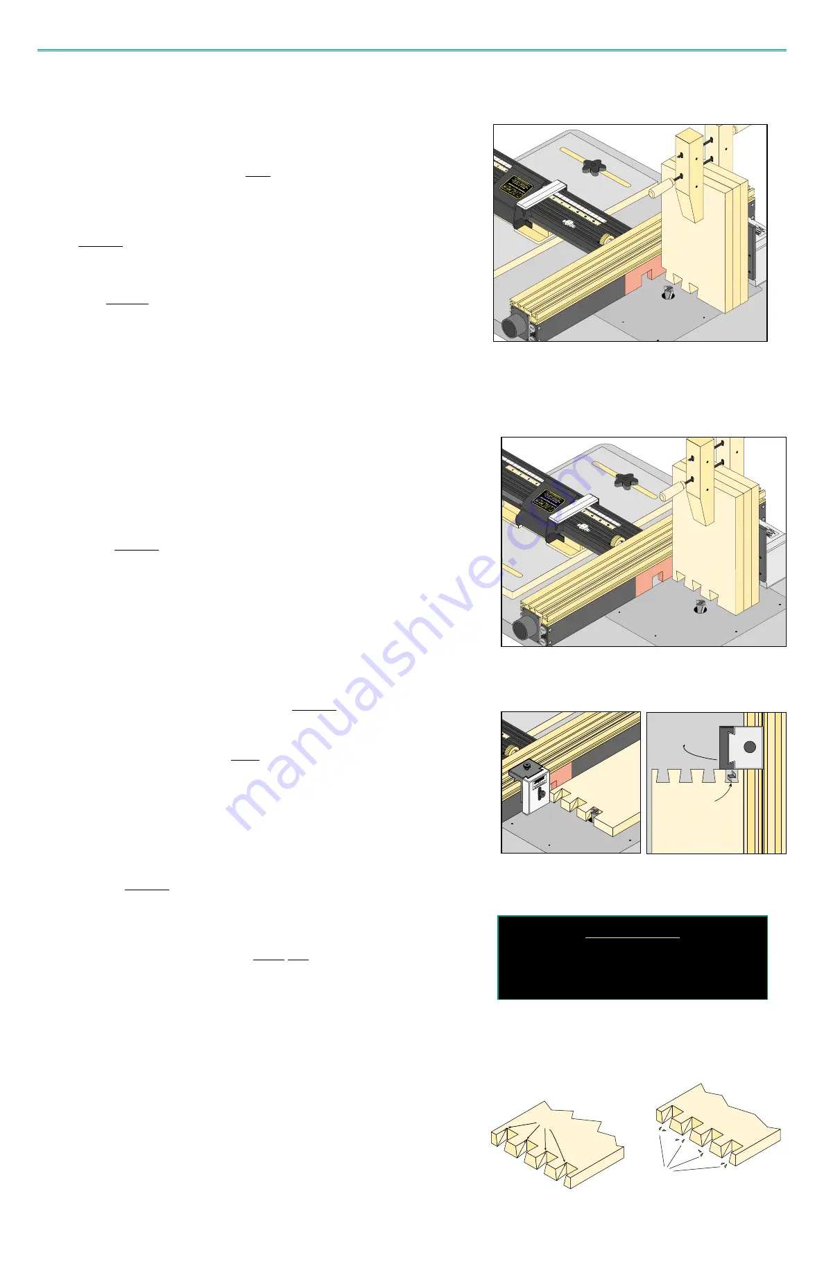
THE VERTICAL CUT
Just as in making the tails use the VPF, Stop Block and a backup board to
prevent splintering. Be sure the end of the workpieces are down on the table
top and the
reference edge is against fence. Several pin boards may be
stacked together for cutting in one pass.
b.
THE HORIZONTAL CUT
This step requires a sliding cut to be made into each dovetail pin cut made in
the previous step. It is important to use the Stop Block to limit the length of
this cut. The preciseness of this cut is especially important since you will be
removing a very small sliver of material to create the straight cut required of a
through dovetail. The steps that follow will insure that you will have a perfect
fit, perfect appearance and an even fit at the ends of the joint.
NOTE: This operation will also require that the reference edge of each
board be placed against the fence for making cuts on both ends.
This means that cuts on one end of the board will be made from
the infeed side of the fence. This cut will have to be made with the
Stop Block placed on the infeed side of the cutter.
(1) Set CLINCHER to a pin cut on the template.
(2) Orient the dovetail bit as shown so that its cutting edges are parallel to
the fence.
(3) Place the pin workpiece flat on the table and slide forward until it just
contacts the bit cutting edge at the inside back edge of the dovetail cut.
Move the workpiece back approximately 1/64” and lock the Stop Block
in position.
(4) Place the
reference edge of the pin workpiece against the fence. Use a
rubber-soled push block and perform the series of sliding cuts to this one
end of board only.
(5) Repeat all the above steps for the other end of each pin piece except all
the cuts will be made from the outfeed toward the infeed side of the cutter
with the Stop Block located on the infeed side.
Even though you are
removing only a small sliver of material in this cut, it is in the “WRONG”
direction for the rotation of the bit. Exercise great care to hold the workpiece
firmly against the fence to prevent the bit from grabbing and throwing the
workpiece away from the fence.
6. Making the Tails
The tails are made with all the cuts through the end grain with the boards vertical and at
right angles to the table and the fence. Use the following procedure and the assigned
template lines to make the tail boards.
NOTE: Some through dovetail template patterns require the CLINCHER to be
micro-adjusted to a
1
/
64”
setting prior to making the tail cuts. If called for on
the full-size plan page, this will be a one-time adjustment made before
starting the series of cuts. The adjustment is made by turning the
thumbwheel to the
1
/
64”
setting.
(1) Clamp your tail boards to the Vertical Push Fixture with a backing board and
reference edge against fence as shown. Be sure the work is down against the
table top and against the fence to keep it square. Set your Stop Block to stop
the VPF before it can be damaged by the bit.
(2) Perform the series of tail cuts. Flip the boards end for end and repeat the same
cuts. NOTE: The first cut on the tail board will be an open cut meaning that
you will be cutting away the edge of the board adjacent to the fence. To prevent
this first cut from splintering, make the cut in several side by side passes.
(3) After completing all the tail cuts rotate the thumbwheel back to the Zero position.
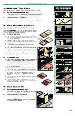
8. The Final Fit
On the face side of the pin workpiece you will notice a very small nub remaining. This is
due to the radial cut of the bit and will be more or less pronounced depending on how
closely your board thickness matches the depth of cut.
With soft woods this nub will cold-form to a straight line and be virtually unnoticed.
However, this is not the case with a hard species of wood. If the appearance of the pin
face is important to you remove the tiny nub with a sharp knife.
C
CA
AU
UT
TI
IO
ON
N
Do not lift the workpiece to clear the
chips or for any other reason with
the wood over the cutter.
Position Stop Block
so that router bit
does not cut into
this flat surface.
Stop Block
Remove small nub left
from router bit.
Waste
17

