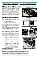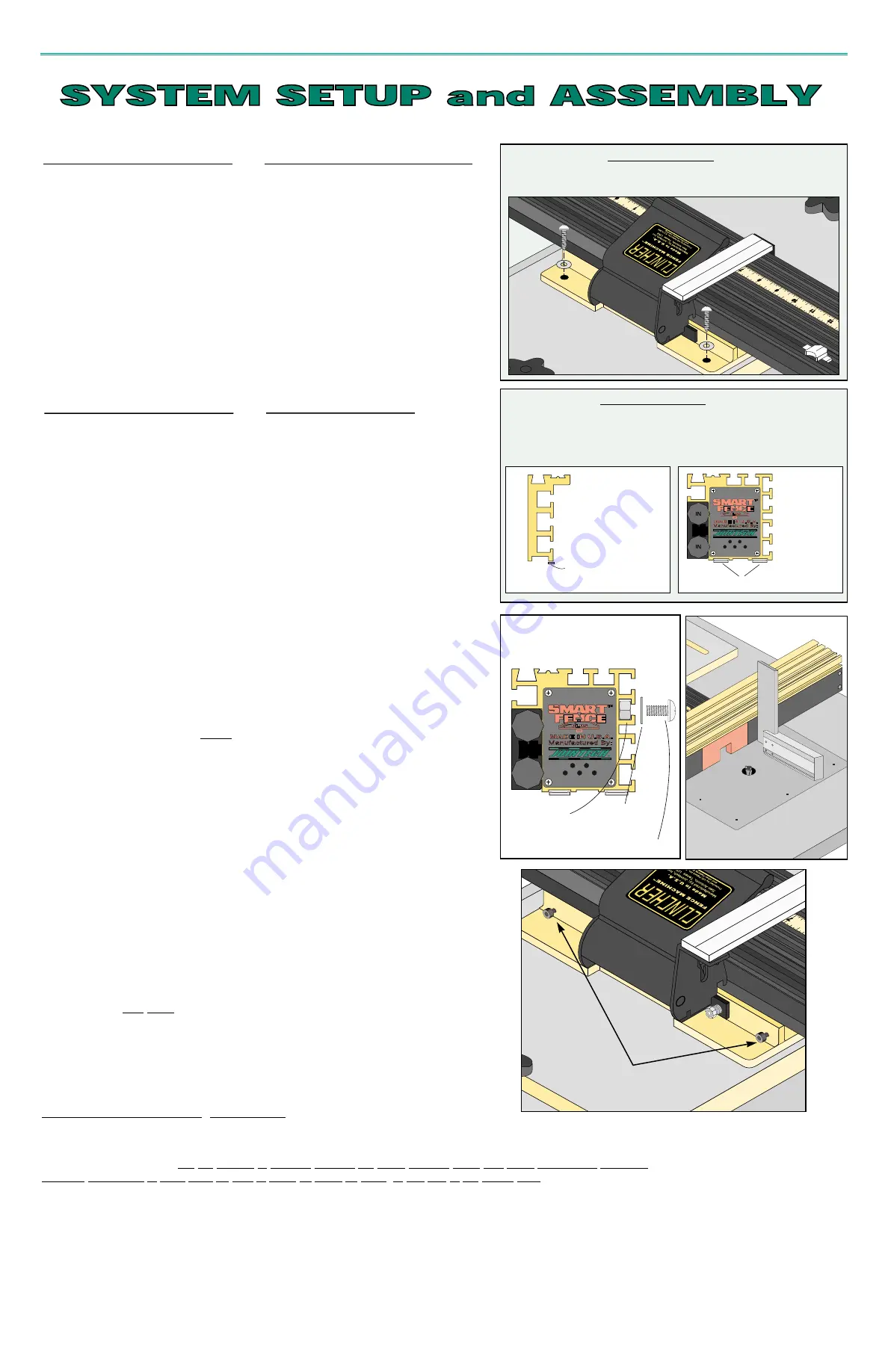
Fasten the
CLINCHER machine directly to your worktop surface or to a
movable base using the wood screws and washers provided. A movable base
should be
1
/
2”
to
3
/
4”
thick (
1
/
2”
maximum when using Joinery Fence), 8 - 10
inches wide and about as long as your top is wide if you plan to use C-clamps.
A slotted baseboard with carriage bolts and clamping knobs is easier to use
and provides a more finished appearance to your setup. Regardless of method,
the
CLINCHER must be mounted to an absolutely flat surface for optimum
performance and to prevent binding of carriage during movement. Additionally,
the fence mounting end of machine must remain parallel to table surface over
its entire range to prevent binding of fence against table surface. Check each
corner before tightening screws and add shims as necessary to achieve this
important first step. Check carriage movement and parallelism after tightening
screws.
Mounting Clincher
Fasteners Supplied
4 ea. - #10 x
3
/
4”
wood screws
4 ea. - #10 flat washer
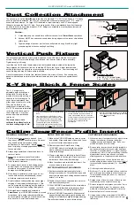
1. Adhere an adhesive-backed nylon glide piece to bottom surface of fence at
each end. Position them so that they contact the table surface near its outer
edges;
For Joinery Fence, cut the glide pieces into narrow
strips and place only on rear edges of fence.
For SmartFence, cut into four short pieces and place
into the front and back shallow slots on bottom of fence.
2. Attach fence to the
CLINCHER fence mounting plate using the two 1/4-20
machine screws, flat washers and heavy hex nuts provided. Insert the two
nuts into the appropriate T-slot and slide toward center. (On SmartFence,
you may need to temporarily remove the two small fence-section clamping
knobs from one side.)
3. With the
CLINCHER fence machine securely mounted in place, align the
exact center of fence to the center of your router, insert screws with washers
through fence mounting plate to engage nuts and tighten. Check for
squareness of fence face to your table top. (With the SmartFence, you want
the square to touch the center of the black split sections since they protrude
out from the main fence by .005” - .010”.) It may be necessary to use shims
between machine and fence to achieve this one-time setup. You can use
adhesive-backed tape as shim stock adhering it to the fence mounting plate.
Move the
CLINCHER to the center of its range before final tightening of
screws.
4. Move
CLINCHER back and forth over its entire range to check for a smooth
travel without lifting or binding. Any dragging or binding over all or part of
the range may be a indication that the machine was not mounted level and
true or that there is a slight unevenness or twist in the table’s surface. This
condition can be corrected by one of two ways;
a) At the center of the
CLINCHER’S range, loosen fence fastening
hardware and temporarily place a thin shim under each fence
end under glide strip (or under the side that binds) to slightly
raise fence.
Re-tighten screws, remove shim and check movement again.
Repeat with a thicker shim and/or at different fence positions if
necessary.
b) Reduce gib tension on
CLINCHER. The two outer #10-32
socket cap screws on the base at back of machine determine
the freedom of
CLINCHER movement in the unclamped state.
Tightening of these two screws will restrict movement while a
very slight loosening of each will allow a more free movement
and alleviate binding of the fence. (Loosening of these gib
adjustment screws will not affect the performance during
micro-adjust or clamping force in the fully locked position of
cam handle. However, cutting SmartFence profile inserts
becomes more of a challenge when the fence has excessive
side-to-side play in its micro-adjust or unlocked position).
Fasteners Supplied
1 ea.
Nylon glide strip, 2
1
/
2”
long
2 ea.
1/4-20 x
1
/
2”
machine screw
2 ea.
1
/
4”
flat washer
2 ea.
1/4-20 nut, heavy hex
IN
IN
Mounting Fence
4
IMPORTANT NOTE:
It is VERY IMPORTANT that you follow the above steps to minimize friction in your final fence setup. When you place the
Cam-handle in its micro-adjust or fully locked position, you are engaging the 1/32” threads of a brass quarter-nut to the
stainless steel lead screw. For the threads to properly engage, the entire carriage setup with fence accessories (including
attached workpieces to VPF) must be able to move as much as 1/64”, or half that of the thread pitch. This engagement will
take place if you have followed the procedure above. However, if there is excessive friction in your system due to binding of
the fence or carriage, then it is possible that the threads may not fully engage and mesh together.
Therefore, take all the initial steps necessary to establish your fence machine setup to have the least amount of friction
possible. To insure that you achieve proper thread engagement it is also suggested that you visually check each setting by
carefully observing that the cursor hairlines are coincident to every template cut line or scale marks in the micro-adjust
position and after locking the cam handle. If you do not get proper engagement in the micro-adjust position, simply nudge the
carriage left or right with your hand.
Nylon Glide
Nylon Glides
1/4-20 nut
1/4-20 screw
flat washer
Gib Adjustment Screws
Joinery Fence
SmartFence


