SYSTEM SETUP and ASSEMBLY
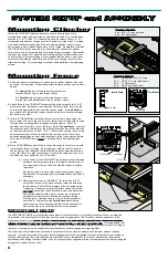
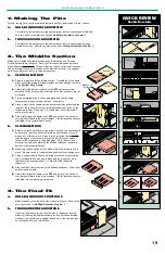
The vacuum port on the SmartFence is the size of a standard 1
1
/
4”
P.V.C. pipe. When a 1
1
/
4”
fitting
such as an elbow is attached, the O.D. is 2 inches which will accommodate most 2”, 2
1
/
4”
and 2
1
/
2”
hoses with hose clamps. If a larger O.D. is desired or required simply use PVC bushings and
fittings to increase the final O.D. size. For a more perfect fit to a non-standard hose duct tape may
be used to build up its outside diameter. P.V.C. fittings are available in most hardware stores and
home improvement centers.
Notes:
1.
A standard shop vac should have sufficient vacuum for all SmartFence operations.
2.
Vacuum MUST be used continuously when doing edge work to prevent chip buildup
within fence.
3.
Tapered design of vacuum port on fence will provide a snug fit with only light
pressure applied when connecting hose fitting.
Dust Collection Attachment
The black anodized aluminum face plate is attached to the VPF frame with the four drywall
screws. Start all four screws through the plate and into the pilot holes in frame assembly.
Tighten evenly until snug.
Insert the two 1/4-20 nylon thumbscrews into the threaded holes located at the top inside
frame adjacent to the dovetail runner. Install the VPF onto the fence. Adjust thumbscrews
until both just touch fence surface to remove side-to-side play of fixture. Over tensioning will
cause binding and may lift fixture entirely off table.
Check for squareness of fixture from table surface and from face of fence. If necessary, use
adhesive-backed tape as shim stock between frame and face plate to achieve squareness of
fixture.
Vertical Push Fixture
Fasteners Supplied
4 ea. - #6 x 1
1
/
4”
drywall screw
2 ea. - 1/4-20 x 1” nylon thumbscrew
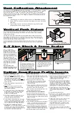
The X - Y stop block is
adjustable both vertically and
horizontally. Two scales are
provided for accurate setting of
the stop to limit the length of a
cut at a precise distance from
either edge or center of a cutter.
They can be found in the
template set immediately after
No. 57. The scales are installed
in the top of the fence next to
the dovetail slot. Cut off any
excess after their installation
into fence.
The steps shown here
calibrate the outfeed scale to
the front cutting edge of bit.
1.
Orient bit cutting edges to run parallel with
fence.
2.
Insert stop block on infeed side of fence.
Lower the sliding vertical section and slide
stop forward on fence until its front edge
just contacts the outer cutting edge of bit.
Temporarily tighten top thumbscrew..
3.
Slide outfeed scale under stop block and
align its Zero to the front edge of stop block.
4.
Loosen top thumbscrew. Raise vertical
section and slide stop block forward on
fence until centered over bit. Lower the
vertical section to allow a small clearance
between bottom edge and top of bit.
Securely lock in place with side
thumbscrew.
5.
Now set the desired length of cut by sliding
the stop block forward and reading the scale
at the back edge of stop.
Cutting SmartFence Profile Inserts
GENERAL INFORMATION
1. Profile inserts do not have to be used. Also,
they do not offer any benefit in joinery. However,
they do add safety and improve cutting
performance for most cutters. Inserts cannot be
used for jointing or shaping operations whenever
fences are offset.
2. Always align centerlines of insert and fence to
center of router.
3. Never turn on router when cutter is within
profile of insert without first manually turning
cutter to insure clearance.
4. To remove insert, loosen infeed sliding section
and pull apart. If necessary, use a slot blade
screwdriver to pry apart. Be careful not to
damage or nick sliding section.
5. Once fence is centered to cutter, if you do not
loosen both sections simultaneously, inserts
will always remain centered to router.
6. Certain intricate cutter profiles may cause slight
chipping of insert when initially being cut. This
can be prevented by clamping a scrap board on
fence to bridge insert and cutting through both.
7. With blank insert installed and centered in
SmartFence, your
CLINCHER machine is moved
forward and into running cutter until profile has
been completely cut through. Profile inserts can
also be cut on a scroll saw or band saw.
SETUP FOR CUTTING
1. Move entire
CLINCHER setup as close to cutter
as possible. Align centerlines of insert and fence
to center of cutter and clamp in place.
2. Remove insert from SmartFence. Using
CLINCHER, move fence forward to a position
where cutter would have profiled the insert
completely through.
3. Clamp a stop block on table top in front of fence
at this position to limit length of travel to protect
inside rear of fence body from damage.
4. Move fence back and re-install blank insert. You
are now ready to make your cut.
CUTTERS WITHOUT BEARINGS
1. First determine the precise height of cutter
through trial and error. This should be done with
insert removed and each sliding section closed to
within
1
/8
”
of cutter.
2. Position fence close to cutter and turn on router
and dust collection system.
3. With
CLINCHER cam handle in the micro-adjust
position, use its thumbwheel to advance fence
until cutter passes completely through insert.
4. Unlock
CLINCHER cam handle. Make several
passes through insert while gently pushing and
pulling fence laterally to slightly enlarge opening.
This will make it easier to use in future setups.
CUTTERS WITH BEARINGS
1. Without an insert, first determine the height of cutter
through trial and error. Measure this height
including bearing and threaded stud. Save your
profiled workpiece for a later setup.
2. Remove cutter from router and install a straight bit
having same diameter as the rub-collar bearing on
the cutter. Set approximately
1
/
16”
higher than your
measurement. Note; A straight bit having a smaller
diameter than bearing may be used by making
offsetting passes to compensate for the difference.
3. Replace blank insert. Loosen both infeed and
outfeed sliding sections and shift the insert to left of
fence centerline by approximately
1
/
64”
. Secure in
place.
4. Cut through insert with straight bit.
5. Shift insert
1
/
64”
to the right side of fence centerline
and cut through insert again to widen the opening.
This procedure should give about
1
/
32”
clearance
around bearing.
6. Realign center of insert to center of fence so that
cutter bearing will be centered to opening.
7. Remove straight bit and replace your cutter. Set to
height established in step 1 by using your scrap
workpiece made during your trial and error setup.
8. Make the final cut of insert with cutter.
9. Using a straight edge, micro-adjust
CLINCHER to
align bearing flush to face of fence insert for your
final setup.
5
1
1
/
4
”
PVC elbow
2” O.D.
1
1
/
2
”
PVC elbow
Female Bushing
2
3
/
4
”
O.D.
X-Y Stop Block & Fence Scales


