15
JO
NIX
VMC
01
02
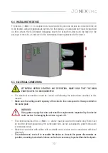
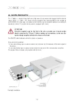
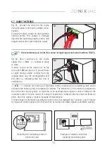
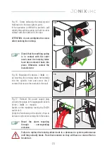
Fig. 01: Connect the device to the mains
using the power cable with suitable cross-
section.
Connect the alarm contact to the machine's
control system. This contact is normally
closed when operating properly and is only
triggered when the system detects a fault.
Fig. 02: Once connected to the mains
supply, the
JO
NIX
VMC
module is ready
to work.
In order to turn on the device act on the
red switch 0/I turning it to I; you will hear
a slight hissing sound coming from the
ionising tubes and the corresponding LED
will light up, indicating that the unit is
switched on.
6.7 USING THE DEVICE
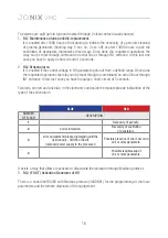
We recommend you to link the contact of input signal and serial interface RS485.
JO
NIX
VMC
devices are made up of electronic control, enclosed in an insulating shell, and of
actuators:the ionising unity are exposed to airflow. The electronics in the device is prepared to
the sent at the central system, in real-time, of an eventual alarm signal in case of failure of the
ionisation system. For this reason, it is easy to implement a software interface that can throw on
video, from this signal, a request message of maintenance.
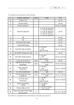
The exchange of informations in entrance and in exit is full managed by 2 sockets, one of 6 poles
for input and control signals (RS 485) and one of 4 ploes for output signals (anomalies signals).
Reporting led functioning state on
electronic card
Example of remote connection
reporting functioning state

