9
JO
NIX
VMC
4 - TECHNICAL DATA
JO
NIX
VMC
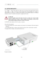
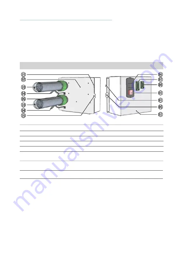
01 Tab wall hooking
06 Electric socket with fuse holder
02 Electric part container
07 Input and serial signal connector
03 Ionising tube
08 Output and alarm reporting connector
04 Attachment form stirrup
09 ON/OFF luminous switch
05 Wall fixing holes
4.1 COMPONENT DESCRIPTION
JO
NIX
VMC
4.1.1 Technical features
JO
NIX
VMC
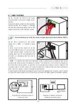
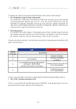
As a result, it is easy to implement a software interface capable of displaying messages requesting
maintenance when this signal is received.
The the
JO
NIX
VMC
modules can therefore be perfectly integrated in aeration systems
commanded by a central control unit.
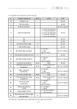
Mod.*
Article
Dimensions
(LxPxH) [mm]
Power Supply
Plasma
generators
Max sprayed
airflow (m
3
/h)
Max power
absorption [W]
Weight
[Kg]
JO
NIX
VMC
70MICVMC2C
160 x 280 x 200 230 V/~1/50Hz 2 x type 175
500
10
2

