background image

26 – 

English

MAINTENANCE

Carburettor

Your Jonsered product has been designed and manufactured 
to specifications that reduce harmful exhaust fumes. The 
engine will be run in after it has used 8-10 tanks of fuel. To 
ensure that the engine runs at peak performance and 
produces as little harmful exhaust fumes as possible after the 
running-in period, ask your dealer/service workshop (which 
has a rev counter for this purpose) to adjust your carburettor.

Carburettor adjustment

The carburettor can be designed in different ways, depending 
on the existing environmental and emissions legislation. 
Some machines are equipped with movement limiters on the 
carburettor’s adjuster screws. These limit the adjustment 
range to a maximum of 1/2 turn.

Function

The carburettor governs the engine’s speed via the 
throttle control. Air and fuel are mixed in the carburettor. 
The air/fuel mixture is adjustable. Correct adjustment is 
essential to get the best performance from the machine.

Adjusting the carburettor means that the engine is 
adapted to local operating conditions, e.g. climate, 
altitude, petrol and the type of 2-stroke oil.

The carburettor has three adjustment controls:

L = Low speed jet

H = High speed jet

T = Idle adjustment screw

The L and H-jets are used to adjust the supply of fuel to 
match the rate that air is admitted, which is controlled with 
the throttle. If they are screwed clockwise the air/fuel ratio 
becomes leaner (less fuel) and if they are turned anti-
clockwise the ratio becomes richer (more fuel). A lean 
mixture gives a higher engine speed and a rich mixture 
gives a lower engine speed.

The T-screw regulates the throttle setting at idle speed. If 
the T-screw is turned clockwise this gives a higher idle 
speed; turning it anti-clockwise gives a lower idle speed.

Basic setting

The basic carburettor settings are adjusted during testing 
at the factory. The basic setting is richer than the optimal 
setting and should be maintained for the first few hours the 
machine is in use. The carburettor should then be finely 
adjusted. Fine adjustment should be carried out by a 
skilled technician.

The basic setting can vary between: H = 1 - 1 1/4 turns 
and L = 1 - 1 1/4 turns.

CAUTION! 

 If the cutting attachment rotates when the engine 

is idling the idle adjustment screw T should be turned anti-
clockwise until the cutting attachment stops.

Rec. idle speed:

 2700 rpm

CAUTION! 

 The machine should only be run for short periods 

at its highest speed. For optimum adjustment of the 
carburettor, contact a qualified dealer/service workshop that 
has a revolution counter at their disposal. 

Recommended max. speed:

 See the Technical data section.

During the running-in period (8-10 tanks of fuel) the maximum 
speed should be set 600-700 rpm below the recommended 
maximum speed (= open the high speed jet H a further 1/8 
turn).

Conditions

Before any adjustments are made, make sure that the air 
filter is clean and the air filter cover is fitted. If you adjust 
the carburettor when the air filter is dirty it will result in a 
leaner mixture when the filter is finally cleaned. This can 
lead to serious engine damage.

Carefully turn both jets, L and H, so that they are midway 
between fully screwed in and fully screwed out.

Do not attempt to adjust the L and H jets beyond either 
stop as this could cause damage.

Now start the machine according to the starting 
instructions and let it warm up for 10 minutes.

CAUTION! 

 If the cutting attachment rotates when the engine 

is idling the idle adjustment screw T should be turned anti-
clockwise until the cutting attachment stops.

Low speed jet L

Try to find the highest idle speed by turning the low speed jet 
L clockwise then anti-clockwise. When the highest speed has 
been found, turn the low speed jet L 1/4 turn anti-clockwise.

CAUTION! 

 If the cutting attachment rotates when the engine 

is idling the idle adjustment screw T should be turned anti-
clockwise until the cutting attachment stops.

!

WARNING! The complete clutch cover and 
shaft must be fitted before the machine is 
started, otherwise the clutch can come loose 
and cause personal injury.

1/2

1/2

H

L

GR41/50  RS44

RS52

!

WARNING! If the idle speed cannot be 
adjusted so that the cutting attachment 
stops, contact your dealer/service 
workshop. Do not use the machine until it 
has been correctly adjusted or repaired.

L

+ 1/4

Summary of Contents for GR41

Page 1: ...GR41 GR50 RS44 RS52 Operator s manual Please read the operator s manual carefully and make sure you understand the instructions before using the machine ...

Page 2: ...etres Machines fitted with saw blades or grass blades can be thrown violently to the side when the blade comes into contact with a fixed object This is called blade thrust The blade is capable of amputating an arm or leg Always keep people and animals at least 15 metres from the machine Always wear approved protective gloves Wear sturdy non slip boots Only use non metallic flexible cutting attachm...

Page 3: ...saw 16 Standard harness 16 Vector harness 16 FUEL HANDLING Fuel safety 18 Fuel 18 Fuelling 19 STARTING AND STOPPING Check before starting 20 Starting and stopping 20 WORKING TECHNIQUES General working instructions 22 MAINTENANCE Carburettor 26 Muffler 28 Cooling system 28 Air filter 28 Bevel gear 29 Spark plug 29 Maintenance schedule 30 TECHNICAL DATA Technical data 31 EC declaration of conformity...

Page 4: ...lers ask for the address of your nearest service workshop It is our wish that you will be satisfied with your product and that it will be your companion for a long time Think of this operator s manual as a valuable document By following its content using service maintenance etc the life span and the second hand value of the machine can be extended If you will sell this machine make sure that the b...

Page 5: ...rottle control 8 Stop switch 9 Throttle lockout 10 Support eyes for harness 11 Cylinder cover 12 Starter handle 13 Fuel tank 14 Choke control 15 Handle adjustment 16 Harness 17 Locking nut 18 Support flange 19 Support cup 20 Drive disc 21 Trimmer head 22 Socket spanner 23 Operator s manual 24 Transport guard 25 Allen key 26 Carburettor screwdriver 27 Locking pin 28 Gearbox grease ...

Page 6: ...rottle control 8 Stop switch 9 Throttle lockout 10 Support eyes for harness 11 Cylinder cover 12 Starter handle 13 Choke control 14 Air filter 15 Fuel tank 16 Socket spanner 17 Handle adjustment 18 Locking nut 19 Support flange 20 Drive disc 21 Transport guard 22 Harness 23 Operator s manual 24 Allen key 25 Locking pin 26 Gearbox grease 27 Carburettor screwdriver ...

Page 7: ...rvice instructions described in this manual Some maintenance and service measures must be carried out by trained and qualified specialists See instructions under the heading Maintenance All covers guards and handles must be fitted before starting Ensure that the spark plug cap and ignition lead are undamaged to avoid the risk of electric shock The machine operator must ensure that no people or ani...

Page 8: ...ockout and make sure it returns to its original position when you release it Check that the throttle control and throttle lockout move freely and that the return springs work properly See instructions under the heading Start Start the machine and apply full throttle Release the throttle and check that the cutting attachment stops and remains at a standstill If the cutting attachment rotates with t...

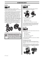
Page 9: ...ituation that requires you to free yourself from the machine and harness See instructions under the heading Adjusting the harness and clearing saw Certain harnesses also have a quick release fitted to the support hook Check that the harness straps are correctly positioned Once the harness and machine have been adjusted check that the harness quick release works correctly Muffler The muffler is des...

Page 10: ...f the saw blade You should therefore always ensure that your hand is shielded by the blade guard when doing this Always use a socket spanner with a shaft that is long enough to allow this The arrow in the diagram shows the area where you should operate the socket spanner when loosening or tightening the nut The nylon lining inside the locking nut must not be so worn that you can turn it by hand Th...

Page 11: ...d grass blades See the cutting attachment packaging for correct sharpening instructions Sharpen blades and cutters using a single cut flat file Sharpen all edges equally to maintain the balance of the blade IMPORTANT Only use cutting attachments with the guards we recommend See the chapter on Technical data Refer to the instructions for the cutting attachment to check the correct way to load the c...

Page 12: ...ed trimmer heads and trimmer cords These have been tested by the manufacturer to suit a particular engine size This is especially important when a fully automatic trimmer head is used Only use the recommended cutting attachment See the chapter on Technical data Smaller machines generally require small trimmer heads and vice versa This is because when clearing using a cord the engine must throw out...

Page 13: ...king position when it hangs from the harness Tighten the knob Assembling the handlebar and throttle RS44 RS52 Unscrew the knob from the handlebar mounting Position the handlebar as shown Fit the mounting components and tighten the knob lightly Fit the right handle to the handlebar using the screw washer sleeve and nut as shown Tighten Put on the harness and hang the machine from the support hook N...

Page 14: ... the drive disc B on the output shaft Turn the blade shaft until one of the holes in the drive disc aligns with the corresponding hole in the gear housing Insert the locking pin C in the hole to lock the shaft Place the blade D and support flange F on the output shaft Fit the nut G The nut must be tightened to a torque of 35 50 Nm 3 5 5 kpm Use the socket spanner in the tool kit Hold the shaft of ...

Page 15: ...rresponding hole in the gear housing Insert the locking pin C in the hole to lock the shaft Screw on the trimmer head H in the opposite direction to the direction of rotation Tighten the trimmer head to a torque of 35 50 Nm 3 5 5 kpm To dismantle follow the instructions in the reverse order Fitting other guards and cutting attachments Fit the trimmer guard combination guard A intended for use with...

Page 16: ...lation to the ground Adjust the height using the strap on the harness for the support hook 2 Grass clearing The machine should be supported in a harness when grass clearing so that the cutting equipment is parallel to the ground Vector harness Safety release Push down the red release lever to release the machine from the harness Adjusting the harness 1 Tighten the hip strap so that it sits securel...

Page 17: ... the shoulder straps to the hip strap Correct balance 1 Forestry clearing The machine is balanced by moving the suspension ring on the machine forwards or backwards On some models the suspension ring is fixed however this will then have a number of holes for the support hook The machine is correctly balanced when it freely hangs horizontally from the support hook In this way the risk of hitting st...

Page 18: ...t the ratio of the mixture Petrol CAUTION Always use a quality petrol oil mixture at least 90 octane RON If your machine is equipped with a catalytic converter see chapter on Technical data always use a good quality unleaded petrol oil mixture Leaded petrol will destroy the catalytic converter Use low emission petrol also known as alkylate petrol if it is available The lowest octane recommended is...

Page 19: ... Contamination in the tank can cause operating problems Ensure that the fuel is well mixed by shaking the container before filling the tank WARNING The catalytic converter muffler gets very hot during and after use This also applies during idling Be aware of the fire hazard especially when working near flammable substances and or vapours WARNING Taking the following precautions will lessen the ris...

Page 20: ...e not damaged or cracked Replace the trimmer head or trimmer guard if they have been exposed to impact or are cracked Never use the machine without a guard nor with a defective guard Starting and stopping Cold engine Ignition Set the stop switch to the start position Choke Set the choke control in the choke position Warm engine Use the same starting procedure as for a cold engine but without setti...

Page 21: ...lling the cord until the engine starts When the engine starts return choke control to run position and apply full throttle the throttle will automatically disengage from the start setting CAUTION Do not pull the starter cord all the way out and do not let go of the starter handle when the cord is fully extended This can damage the machine Stopping Stop the engine by switching off the ignition WARN...

Page 22: ...uard before carrying or transporting the equipment any distance 10 Never put the machine down with the engine running unless you have it in clear sight The ABC of clearing Always use the correct equipment Make sure the equipment is well adjusted Follow the safety precautions Organise your work carefully Always use full throttle when starting to cut with the blade Always use sharp blades Avoid ston...

Page 23: ... right Tilt the blade and bring it diagonally down to the right exerting firm pressure At the same time push the stem using the blade guard Cut with the area of the blade between 3 o clock and 5 o clock Apply full throttle before advancing the blade To fell to the right the bottom of the tree should be pushed to the left Tilt the blade and bring it diagonally up to the right Cut with the area of t...

Page 24: ... the stems to the required height Now try to reach in with the blade and cut from the centre of the group If it is still difficult to gain access cut the stems high up and let them fall This will reduce the risk of jamming Grass clearing using a grass blade Grass blades and grass cutters must not be used on woody stems A grass blade is used for all types of tall or coarse grass The grass is cut do...

Page 25: ...rd wears quicker and must be fed forward more often when working against stones brick concrete metal fences etc than when coming into contact with trees and wooden fences When trimming and clearing you should use less than full throttle so that the cord lasts longer and to reduce the wear on the trimmer head Cutting The trimmer is ideal for cutting grass that is difficult to reach using a normal l...

Page 26: ...ment should be carried out by a skilled technician The basic setting can vary between H 1 1 1 4 turns and L 1 1 1 4 turns CAUTION If the cutting attachment rotates when the engine is idling the idle adjustment screw T should be turned anti clockwise until the cutting attachment stops Rec idle speed 2700 rpm CAUTION The machine should only be run for short periods at its highest speed For optimum a...

Page 27: ...peed is not changed but only causes the engine to receive too little fuel resulting in a large risk of engine failure Run the machine warm for approximately 5 minutes alternating between short intervals of full throttle and idling When the carburettor is to be adjusted apply full throttle and turn the H needle anti clockwise until the engine speed reaches 10 500 11 000 r min burbles or until the c...

Page 28: ...ystem To keep the working temperature as low as possible the machine is equipped with a cooling system The cooling system consists of 1 Air intake on the starter 2 Fins on the flywheel 3 Cooling fins on the cylinder 4 Cylinder cover directs cold air over the cylinder Clean the cooling system with a brush once a week more often in demanding conditions A dirty or blocked cooling system results in th...

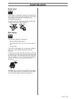
Page 29: ... much or incorrect type of oil A dirty air filter These factors cause deposits on the spark plug electrodes which may result in operating problems and starting difficulties If the machine is low on power difficult to start or runs poorly at idle speed always check the spark plug first before taking any further action If the spark plug is dirty clean it and check that the electrode gap is 0 5 mm Th...

Page 30: ...locking screw is tightened when using a support cup with bearings X Check that the transport guard for the blade is intact and that it can be secured correctly X Check that nuts and screws are tight X Check that there are no fuel leaks from the engine tank or fuel lines X Check the starter and starter cord X Check that the vibration damping elements are not damaged X Clean the outside of the spark...

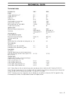
Page 31: ... engine output acc to ISO 8893 1 8 9000 2 1 9000 Catalytic converter muffler No No Ignition system Manufacturer type of ignition system EM ET EM ET Spark plug NGK BPMR 7A Champion RCJ 7Y NGK BPMR 7A Champion RCJ 7Y Electrode gap mm 0 5 0 5 Fuel and lubrication system Manufacturer type of carburettor Zama C1Q Zama C1Q Fuel tank capacity litre 0 8 0 8 Weight Weight without fuel cutting attachment an...

Page 32: ...tput acc to ISO 8893 2 0 9000 2 4 9600 Catalytic converter muffler No No Ignition system Manufacturer type of ignition system EM ET EM ET Spark plug NGK BPMR 7A Champion RCJ 7Y NGK BPMR 7A Champion RCJ 7Y Electrode gap mm 0 5 0 5 Fuel and lubrication system Manufacturer type of carburettor Zama C1Q Walbro HDA Fuel tank capacity litre 0 8 0 75 Weight Weight without fuel cutting attachment and guard...

Page 33: ...GR50 SEC 94 062 01 164 025 RS44 SEC 99 657 01 164 025 RS52 Huskvarna January 3 2002 Bo Andréasson Development manager GR41 GR50 Approved accessories Type Cutting attachment guard Art no Centre hole in blades cutters Ø 20 mm Output shaft thread M12 Grass blade grass cutter Multi 255 3 Ø 255 3 teeth 502 26 34 03 Grass 275 4 Ø 275 4 teeth 502 26 34 03 Multi 275 4 Ø 275 4 teeth 502 26 34 03 Multi 300 ...

Page 34: ...1 Poly Trim 2 3 4 5 6 7 8 20mm 20mm B A 6 Nm X 10 ...

Page 35: ...1 2 3 4 5 6 7 8 9 35 50 NM 15 cm 6 Clic 3 5 m 11 7 0 m 23 2 4 3 3 mm 095 130 12 cm 5 Trimmy SII ...

Page 36: ......

Page 37: ...2 7 3 3 mm 106 130 15 cm 6 15 cm 6 15 cm 6 15 cm 6 1 2 3 5 6 7 10 11 1 2 1 1 Kw 1 1 Kw 2 7 mm 9 0 m 3 0 mm 7 5 m 3 3 mm 6 0 m 4 8 Auto 55 ...

Page 38: ... z Rq 60 z Rq 60 Clic 1 2 3 5 6 7 9 10 m 32 4 8 4 3 m 14 2 7 3 3 mm 106 13 10 cm 4 6 15 cm Tap n Go 45 ...

Page 39: ......

Page 40: ... z Rq 60 2007 04 02 z Rq 60 1150811 26 ...

Reviews: