background image

5

OPERATION

WARNING:

Be sure to read the fuel

information in the safety rules before you be-

gin. If you do not understand the safety rules,

do not attempt to fuel your unit. Contact an

authorized service dealer.

FUELING ENGINE

WARNING:

Remove fuel cap slowly

when refueling.
This engine is certified to operate on un-

leaded gasoline. Before operation, gasoline

must be mixed with a good quality synthetic

2-cycle air-cooled engine oil designed to be

mixed at a ratio of 40:1 (2.5%). A 40:1 ratio is

obtained by mixing 5 liters of unleaded gaso-

line with 0,125 liter of oil. DO NOT USE auto-

motive oil or boat oil. These oils will cause en-

gine damage.

When mixing fuel, follow

instructions printed on oil container. Once oil

is added to gasoline, shake container mo-

mentarily to assure that the fuel is thoroughly

mixed. Always read and follow the safety

rules relating to fuel before fueling your unit.

IMPORTANT

Experience indicates that alcohol blended

fuels (called gasohol or using ethanol or

methanol) can attract moisture which leads to

separation and formation of acids during stor-

age. Acidic gas can damage the fuel system

of an engine while in storage. To avoid engine

problems, empty the fuel system before stor-

age for 30 days or longer. Drain the gas tank,

start the engine and let it run until the fuel lines

and carburetor are empty. Use fresh fuel next

season. Never use engine or carburetor

cleaner products in the fuel tank or permanent

damage may occur.

HOW TO STOP YOUR UNIT

S

To stop the engine, move the ON/OFF

switch to the OFF position.

HOW TO START YOUR UNIT

WARNING:

The trimmer head will

turn while starting the engine. Avoid any con-

tact with the muffler. A hot muffler can cause

serious burns.

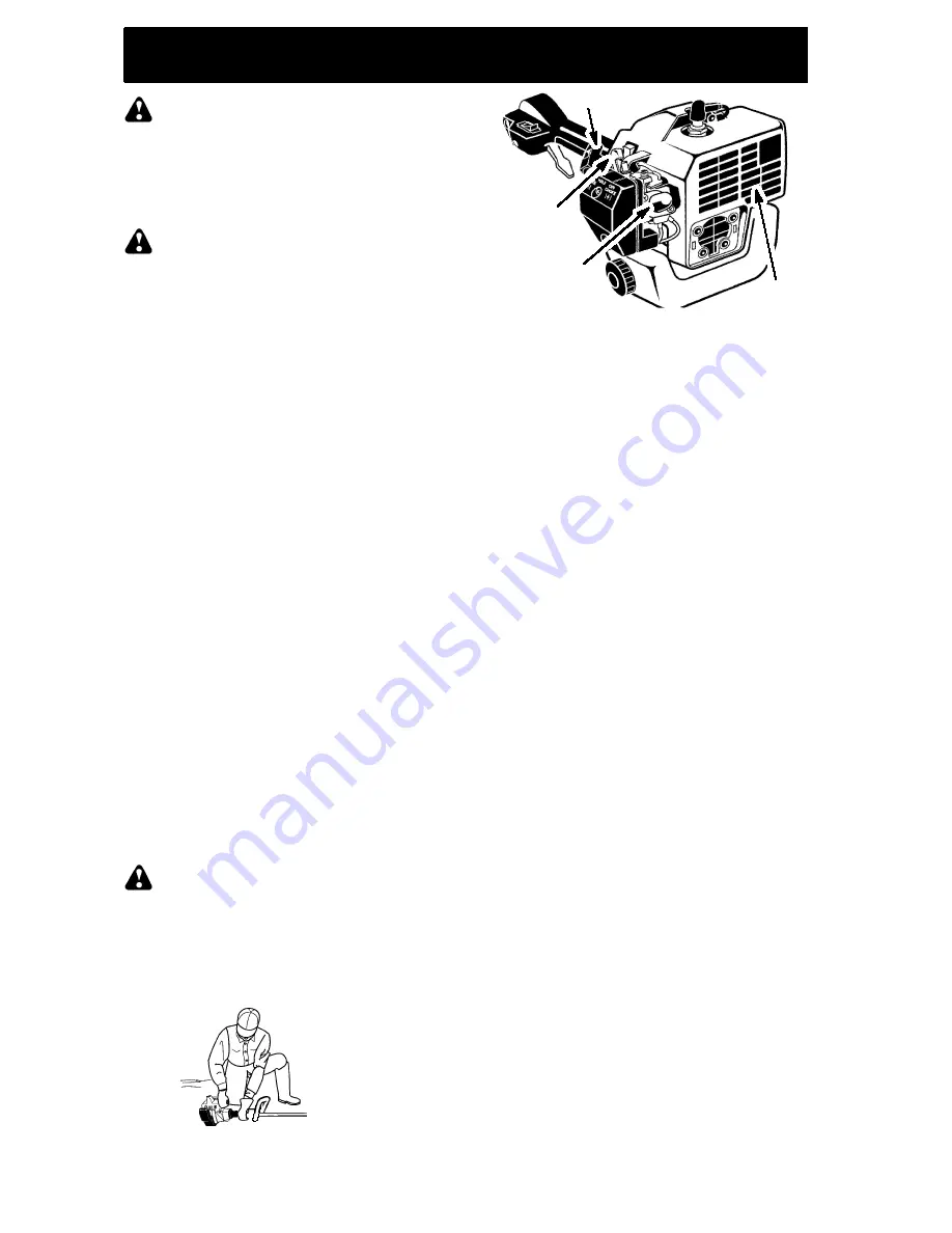
STARTING A COLD ENGINE (or a

warm engine after running out of fuel)

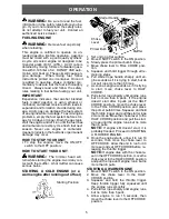
Starting Position

Choke

Lever

Primer Bulb

Starter Handle

Muffler

1. Set unit on a flat surface.

2. Move ON/OFF switch to the ON position.

3. Slowly press the primer bulb 6 times.

4. Move choke lever to FULL CHOKE posi-

tion.

5. Squeeze and hold trigger through

all re-

maining steps

.

6. Pull starter rope handle sharply until en-

gine sounds as if it is trying to start, but do

not pull rope more than 6 times.

7. As soon as engine sounds as if it is trying

to start, move choke lever to HALF

CHOKE.

8. Pull starter rope sharply until engine runs,

but no more than 6 pulls. If the engine

doesn’t start after 6 pulls (at the HALF

CHOKE position), move the choke lever

to the FULL CHOKE position and press

the primer bulb 6 times. Squeeze and hold

the throttle trigger and pull the starter rope

2 more times. Move the choke lever to the

HALF CHOKE position and pull the start-

er rope until the engine runs, but no more

than 6 pulls.

NOTE:

If engine still doesn’t start, it is

probably flooded. Proceed to STARTING

A FLOODED ENGINE.

9. Once the engine starts, allow it to run 10

seconds, then move the choke lever to

OFF CHOKE. Allow the unit to run for 30

more seconds at OFF CHOKE before re-

leasing the throttle trigger.

NOTE:

If engine dies with the choke le-

ver in the OFF CHOKE position, move the

choke lever to the HALF CHOKE position

and pull the rope until engine runs, but no

more than 6 pulls.

STARTING A WARM ENGINE

1. Move ON/OFF switch to the ON position.

2. Move the choke lever to the HALF

CHOKE position.

3. Squeeze and hold the throttle trigger.

Keep throttle trigger fully squeezed until

the engine runs smoothly.

4. Pull starter rope sharply until engine runs,

but no more than 5 pulls.

5. Allow engine to run 15 seconds, then

move the choke lever to the OFF CHOKE

position.

Summary of Contents for GT25L

Page 1: ... averle comprese prima di usare l unità 530088141 1 9 02 Deutsch Italiano Español Instruction Manual Manuel d instructions English Français Please read these instructions carefully and make sure you understand them before using this unit Avant d utiliser cet appareil veuillez lire attentive ment les instructions et assurez vous de les avoir comprises ENGLISH FRANÇAIS DEUTSCH ITALIANO ESPANOL Lees ...

Page 2: ...this tool D WARNING The trimmer line can throw objects violently You can be blinded or injured Always wear eye protection E Always use Ear protection Protective glasses or visor F Assist handle to be positioned only below the arrow G The operator of the machine must insure that no one comes within a 15 meter radius while working When several operators are working within the same area a safety dis ...

Page 3: ...clothing or clothing with loosely hanging ties straps tassels etc They can be caught in moving parts S Being fully covered also helps protect you from debris and pieces of toxic plants thrown by spinning line S Stay Alert Do not operate this unit when you are tired ill upset or under the influence of al cohol drugs or medication Watch what you are doing use common sense S Wear hearing protection S...

Page 4: ...therwise healthy people If symptoms occur such as numbness pain loss of strength change in skin color or texture or loss of feeling in the fingers hands or joints discontinue the use of this tool and seek med ical attention An anti vibration system does not guarantee the avoidance of these prob lems Users who operate power tools on a continual and regular basis must monitor closely their physical ...

Page 5: ...ffler A hot muffler can cause serious burns STARTING A COLD ENGINE or a warm engine after running out of fuel Starting Position Choke Lever Primer Bulb Starter Handle Muffler 1 Set unit on a flat surface 2 Move ON OFF switch to the ON position 3 Slowly press the primer bulb 6 times 4 Move choke lever to FULL CHOKE posi tion 5 Squeeze and hold trigger through all re maining steps 6 Pull starter rop...

Page 6: ...eter line Other sizes and shapes of line will not ad vance properly and will result in improper cut ting head function or can cause serious injury Do not use other materials such as wire string rope etc Wire can break off during cutting and become a dangerous missile that can cause serious injury CUTTING METHODS WARNING Use minimum speed and do not crowd the line when cutting around hard objects r...

Page 7: ...t if debris shield is damaged INSPECT AND CLEAN UNIT AND LABELS S After each use inspect complete unit for loose or damaged parts Clean the unit and labels using a damp cloth with a mild deter gent S Wipe off unit with a clean dry cloth CLEAN AIR FILTER A dirty air filter decreases engine perform ance and increases fuel consumption and harmful emissions Always clean after every 5 hours of operatio...

Page 8: ...ervice dealer STORAGE WARNING Perform the following steps after each use S Allow engine to cool before storing or trans porting S Store unit and fuel in a well ventilated area where fuel vapors cannot reach sparks or open flames from water heaters electric motors or switches furnaces etc S Empty fuel tank before storing or transport ing the unit S Store unit and fuel well out of the reach of child...

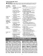
Page 9: ...ill with correct fuel mixture 2 Replace with correct spark plug 3 See Carburetor Adjustment in Service and Adjustments Section 4 Contact an authorized service dealer WARNING Always stop unit and disconnect spark plug before performing all of the recommended remedies below except remedies that require operation of the unit TROUBLESHOOTING TABLE U S EPA ENVIRONMENT CANADA EMISSION CONTROL WARRANTY S...

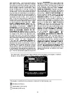
Page 10: ...he first scheduled replacement point for that part DIAGNOSIS The owner shall not be charged for diagnostic labor which leads to the determination that a warranted part is defective if the diagnostic work is performed at an ap proved Jonsered servicing center CONSE QUENTIAL DAMAGES Jonsered may be li able for damages to other engine components caused by the failure of a warranted part still un der ...

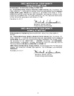
Page 11: ...dards DECLARATION OF CONFORMITY relating to 98 37 EC EU Declaration of Conformity Directive 98 37 EC Annex II A Only applies to Europe We Poulan Weed Eater Division Electrolux North America Inc Texarkana TX 75501 USA Tél 1 903 223 4100 Declare under sole responsibility that the Jonsered model GT25L grass trimmer from serial numbers 2001 305N00001 and onwards follows the provisions of the DIRECTIVE...

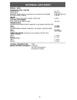
Page 12: ...NG ATTACHMENT Type diameter for trimmer head 108 mm SOUND LEVELS SOUND PRESSURE LEVELS measured in accordance with ISO 7917 Idling 78 dB A Racing 98 dB A SOUND POWER LEVELS measured in accordance with ISO 10884 Idling 89 dB A Racing 108 4 dB A VIBRATION LEVELS measured in accordance with ISO 7916 FRONT HANDLE Idling 1 7 m s2 Racing 6 7 m s2 REAR HANDLE Idling 1 9 m s2 Racing 8 0 m s2 YEAR OF CONST...

Reviews: