FILTER 8
MULTIMODE FILTER/8-PHASE OSCILLATOR
4
10 LOWPASS OUTPUTS
These are the outputs from the different stages
inside the 4-pole lowpass filter core. Frequencies
above the filter frequency (also known as ‘cutoff’,
‘corner’ or ‘centre’) will be attenuated. More
stages means more attenuation, so each output
has its own character: LP1 has the softest filter
response (−6 dB per octave), while LP4 has the
steepest (−24 dB per octave).
Electronic filters do not just affect amplitude, but
phase as well. The phase shift at the filter
frequency, relative to the input signal, is printed
above each socket. Every additional filter stage
adds 45° of phase shift. As a result, the sine waves
generated at the outputs in self-oscillation will
be separated by 45° between adjacent stages.
The LEDs at the output sockets show the real-
time output voltages, lighting up red for positive
and blue for negative. Note that DC offset
voltages may be visible at the outputs, especially
at extremely low frequencies. This is a result of
the circuit topology and is considered normal
behaviour.
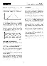
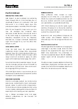
The image below illustrates the amplitude
responses of the four lowpass outputs,
superimposed. The vertical dotted line denotes
the filter frequency; the horizontal unity gain.
Both axis are logarithmic.
11 POLE-MIXING OUTPUTS
Using pole-mixing, additional filter responses are
derived from the standard lowpass stages. The
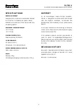
first is a 1-pole highpass output, offering relatively
gentle highpass filtering. It will resonate at 225°.
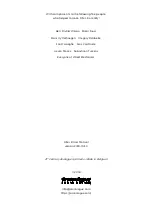
The second pole-mixing output is a special band
boost and notch response. This boosts
frequencies just below the filter frequency, and
cuts those just above it. At high resonance
settings, wavefolder-type sounds can be
generated. It will resonate at 270°.
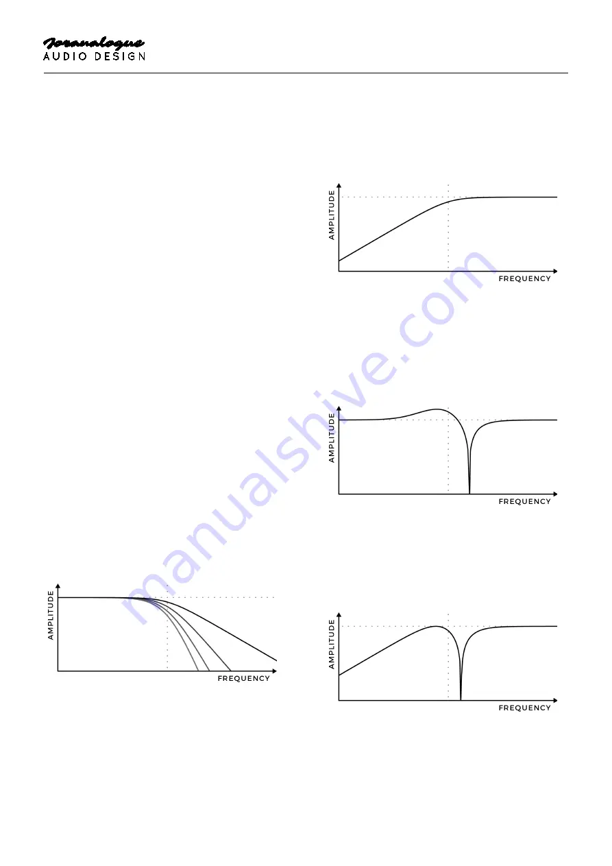
Next is the phase shifter output. It consists of a 3-
pole allpass response, mixed together with the
input signal. This creates a combined highpass
and notch response, essentially a one-stage
phaser effect. It will resonate at 315°.


