background image

-8-

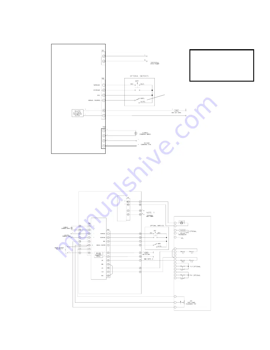
Wiring Diagrams

With AD-7830 Integral to Actuator

With AD-7830 Remote from Actuator

Notes:

1. 240 Vac input is required where actuator nameplate voltage

is 180 Vdc.

2. 24 Vdc power supply is required.

3. VRI potentiometer signal requires conversion to 4-20mA

signal at actuator with 24 Vdc loop power when amplifier

distance from actuator exceeds 50 feet of wiring.

Notes:

1. 240 Vac input is required where

actuator nameplate voltage is 180 Vdc.

2. 24 Vdc power supply is required.

3. When using external Auto/Manual

switch, DIP SWITCH SW1-4 must be

set for manual operation on amplifier.

Due to wide variations

in terminal numbering

of actuator products, actual

wiring should follow the print

supplied with the actuator

.

Note 1

Note 2

Note 3

Summary of Contents for AD-7830

Page 1: ...anual 2 General Description 3 Actuator Compatability 3 Basic Models 3 Specifications 3 Installation Wiring 3 Set up and Calibration 4 5 Component Location 6 Troubleshooting Guide 7 Typical Wiring Diagrams 8 Major Dimensions 9 10 IM 0606 Due to wide variations in the terminal numbering of actuator products actual wiring of this device should follow the print supplied with the unit ...

Page 2: ...e actuator WARNING SHOCK HAZARD Installation and servicing must be performed only by qualified personnel WARNING ELECTROSTATIC DISCHARGE This electronic control is static sensitive To protect the internal components from damage never touch the printed circuit cards without using electrostatic dis charge ESD control procedures RECEIVING INSPECTION Carefully inspect for shipping damage Damage to the...

Page 3: ...ce 0 to 5 0 to 10 Vdc or optionally using EC 10844 for 10 to 10 Vdc command into a 100k ohm impedance Position feedback signal 1000 ohm potentiometer or 4 20 mA switch selectable 4 to 20 mA feedback is normally used for remote amplifier installations Other inputs Position limit switches 2 and torque or thrust limit switches 2 from actuator Auto Manual switch with increase and decrease capabiity No...

Page 4: ... switch Next apply command signal at maximum input value For 4 20mA systems this would normally be 20mA Adjust pot labeled SPAN to move actuator position to correspond with maximum desired position without actuating the end of travel limit switch Some interaction of the above pot settings will require repeating this procedure until proper accuracy is achieved 7 SPEED adjust pot must be set to limi...

Page 5: ...accordingly If move to preset option is selected the preset position must be adjusted now With the servo amplifier in normal operation remove the positive command signal wire from the amplifier The LED labled LOS lights indicating a loss of command signal and the actuator will move to the preset LOS pot setting Slowly adjust the LOS pot until the actuator shaft is in the position desired when loss...

Page 6: ...ion Amplifier Power Board Enclosed in Metal Case Customer Interface Board 50 Pin Ribbon Input Voltage 1 Blue Box Driver Board 68C 038504 001 2 Interface Board 68C 035606 001 3 Ribbon Cable 25A 035285 002 Spare Parts List ...

Page 7: ...perly adjusted a Adjust speed pot as required but not faster than catalog ratings b Bal pot needs adjustment b Adjust Bal pot as required a Input voltage selector switch not in correct position a Correct position as required b 180 Vdc actuators must have 240 Vac input to amplifier b Insure proper power supply is available c Amplifier output voltage jumper selector in wrong position c Correct jumpe...

Page 8: ...t actuator with 24 Vdc loop power when amplifier distance from actuator exceeds 50 feet of wiring Notes 1 240 Vac input is required where actuator nameplate voltage is 180 Vdc 2 24 Vdc power supply is required 3 When using external Auto Manual switch DIP SWITCH SW1 4 must be set for manual operation on amplifier Due to wide variations in terminal numbering of actuator products actual wiring should...

Page 9: ... 9 AD 7830 P Amplifier Mounted on a Panel Major Dimensions AD 7830 R73P Retro fit for AD 7300 Series ...

Page 10: ...als and position torque limit switches Major Dimensions Remote Mount AD 7830 E Installed in remote enclosure NEMA 4 These dimensions are subject to change without notice and should not be used for preparation of drawings or fabrication of installation mounting Current installation dimension drawings are available upon request JORDAN CONTROLS INC 5607 West Douglas Avenue Milwaukee Wisconsin 53218 P...

Reviews: