background image

02.13

7

 Josef Kihlberg JK20T779


6


OPERATING INSTRuCTIONS

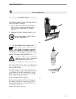
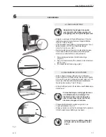
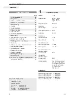
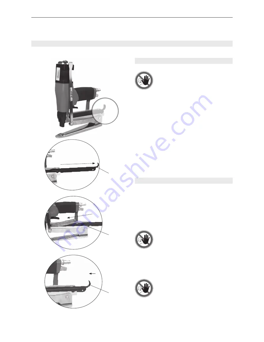
6.1 LOADING THE MAGAZINE

Be sure that the tool is not pointing at

yourself or anyone else when connec-

ting it to the compressed air line.


– Connect the tool to the compressed air line before 

loading staples. The max. allowed air pressure is 7 

bar.


Always use Josef Kihlberg original staples  

JK779 with leg length 08 (5/16“ ) to 16 mm 

(5/8“).


The correct type of staple is marked on the right 

side of the magazine. Ensure you use the right 

length of staples for your application. 

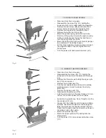
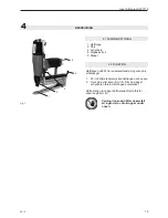
1.  Pull the magazine lid all the way out (Fig. 4/1)

2.  Place the staple strip (4/2) into the staple rail from 

the left hand side.

3.  Place the staple strip into the magazine and push 

the lid (4/3) forward again until it clicks in.

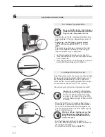
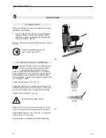
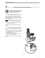
6.2 OPERATING THE STAPLER

Adjust the air pressure to the lowest one that will drive 

the staples to the desired depth. Start at approx. 5.0 

bar (72 psi) and raise this by 0.5 bar (7 psi) incre-

ments until the correct operating pressure for the job 

in hand is found. Never exceed 7 bar (100 psi). 


A low air pressure will give low maintenance costs!


Place the tool firmly on the work surface. Never 

drive staples in extremely hard or brittle material. 

Do not drive staples at too steep an angle or too 

close to the edge of the work: the staples might fly 

free and hurt someone.  


– Pull the trigger as described in chapter 4,2


Move the tolls sideway until you have finished and 

then release the trigger.


Control the clinch, refer to chapter 7.5.

Warning: before stapling, ensure that

your hand or any other part of your 

body is not underneath/between the 

nozzle and anvil.

Always place yourself in a firmly balan

-

ced position when using or handling the 

tool. Do not drive staples at too steep 

an angle or too close to the edge of the 

work: the fastener might fly free and hurt 

someone.

Fig. 4

1

2

3

Summary of Contents for JK20T779

Page 1: ... the tool read the operating in structions carefully Läs igenom bruks anvisningen noga innan du använder klammer verktyget Vor dem Gebrauch des Gerätes die Betriebs anleitung aufmerksam lesen Avant l utilisation de l appareil consultez soigneusement le mode d emploi OPERATING INSTRUCTIONS Translation of original manual BRUKSANVISNING Originalmanual BETRIEBSANLEITUNG Übersetzung der Originalbetrieb...

Page 2: ...68 Staple JK779 10 3 8 Art No 400370 Staple JK779 12 1 2 Art No 400372 Staple JK779 14 9 16 Art No 400373 Staple JK779 16 5 8 Art No 400375 Page 1 Technical data 2 2 General information 3 2 1 Information on environmental protection 3 3 Safety instructions 4 4 Description 5 4 1 Design 5 4 2 Function 5 5 Initial operation 6 5 1 Installation 6 5 2 Compressed air connection Lubrication 6 6 Operating i...

Page 3: ...nd the possibilities of application for the intended purpose The operating instructions contain important information concerning the safe proper and efficient use of the pliers Ob servation of the information will help to avoid danger reduce repairs and stoppages and increase the reli ability and service life of the pliers The operating instructions must always be available at the place of operati...

Page 4: ...s for sevicing task refer also to chapter 7 1 and 7 2 3 Safety instructions Inform yourself Read the operating instructions carefully Protect yourself When operating the stapler wear eye ear protection Warning Danger of crushing Do not put your fingers underneath the nozzle Warning Hazard Lay the compressed air hose so that there is no risk of tripping over it Do not exceed the air pressure Do not...

Page 5: ...lace the tool around the work piece 2 then pull the trigger Fig 1 3 To avoid damage to the driver blade in the tool never fire it without any work piece 4 1 DESIGN 1 Anvil 2 Door 3 Trigger 4 Magazine lid 5 Nipple Fig 1 1 2 3 4 5 Warning before stapling ensure that your hand or any other part of your body is not underneath the nozzle ...

Page 6: ...pressure gauge The internal diameter of the pipe should be at least 10 mm 3 8 Never exceed the maximum permitted air pressure of 7 bar 110 psi The maximum supply pressure is 8 bar 110 psi A low air pressure will give low maintenance costs The stapler and the hose must have a coupling which automatically bleeds all air pressure from the stapler when it is disconnected The stapler needs a small amou...

Page 7: ... one that will drive the staples to the desired depth Start at approx 5 0 bar 72 psi and raise this by 0 5 bar 7 psi incre ments until the correct operating pressure for the job in hand is found Never exceed 7 bar 100 psi A low air pressure will give low maintenance costs Place the tool firmly on the work surface Never drive staples in extremely hard or brittle material Do not drive staples at too...

Page 8: ...d the magazine lid does not open itself all screws and nuts are securely tightened the stapler is regularly lubricated refer to chapter 5 2 Before all maintenance tasks on the stapler always first disconnect it from the air supply To remove a staple which has become jammed Pry the door open with a screw driver Fig 5 1 There are three notches in the door to simplify the disassembling Remove the doo...

Page 9: ...zle and push it down Check that the piston and the driver move freely in the cylinder and in the nozzle Mount the cylinder cap 7 4 Mount the upper cylinder 7 3 and tighten the three screws Turn the power 7 2 arm and assemble the screw 7 1 Disconnect tool from air supply Disassemble the screw Fig 6 1 holding the power arm 6 2 turn it underneath the magazine Remove the rear screw 6 4 and the two fro...

Page 10: ...efore delivery By rough treatment during operation the anvil therefore might need to be adjusted Uncorrect clinching may then occur Fig 9 1 Insert a lose staple into the nozzle Fig 10 1 Unscrew the three screws on the rear of the anvil a 1 4 turn Raise the anvil to the staple edges and adjust it so that the staple hits the anvil hollows sym metrically Then tighten the screws Make a test stapling i...

Page 11: ...e Check if the staple pusher is not defective If necessary replace Clean the staple track Air pressure too low Secure that working pressure is as recommend see chapter 6 2 Adjust the air pressure as chapter 6 2 Has the tool been used without oil Provide lubri cation see chapter 5 2 Fit a longer driver blade Check if the air pressure is correct Adjust as per chapter 6 2 Ensure that the work piece i...

Page 12: ...rigatan 37B SE 544 50 HJO Telefone 46 503 328 00 Fax 46 503 328 01 E mail reception kihlberg se Internet www kihlberg com SVENSKA Vikt 1 9 kg 4 2 lbs Dimension Längd 235 mm 9 3 Bredd 68 mm 2 7 Höjd 250 mm 9 8 Magasinskapacitet 84 klammer Klammerlängd 8 16 mm 5 16 5 8 Noslängd 14 mm 0 6 in Häftdjup 140 mm 5 5 in Max lufttryck 7 bar 100 psi Rekommenderat arbetstryck 5 6 bar 70 85 psi Luftförbrukning...

Page 13: ... men om klammerverktyget och dess handhavande och applikationer Manualen innehåller viktig informa tion angående säkerhet korrekt och effektiv användn ing Genom att iakttaga denna information hjälper det till att förhindra olyckor och reducera reparationer och driftstörningar och förlänga livslängden på tången Manualen skall alltid hållas tillgänglig i arbetsområdet för tången Den skall läsas och ...

Page 14: ...and 7 2 Informera dig Läs igenom bruks anvisningen noga Skyddsutrustning Bär skyddsutrustning för ögon och öron när du använder klammerverk tyget Varning Akta fingrarna Stoppa inte fingrar eller andra kroppsdelar under nosen Varning Snubbelrisk Lägg tryckluftsslangen så att det inte finns någon risk för att snubbla över den Överskrid inte lufttrycket Överskrid inte rekom menderat lufttryck Använd ...

Page 15: ...lan häfttungan och nosen 2 Tryck på avtryckare Fig 1 3 När du släpper avtryckaren returnerar tungan automatiskt Häfta aldrig utan något häftmaterial Detta förstör drivaren på kort tid 4 1 Sammansättning 1 Häfttunga 2 Dörr 3 Avtryckare 4 Magasinslock 5 Nippel Varning innan du häftar säkerställ att ingen del av din kropp är under nosen Fig 1 1 2 3 4 5 ...

Page 16: ...nkluderar vattenavskiljare och luftregulator med manometer och dimsmörjarenhet Som alternativ till detta kan dims mörjolja tillföras i nippeln några droppar dagligen eller ca 10 droppar vecka 733007 Dimsmörjolja 0 2 dl Fig 3 1 Verktygets glidytor har vid tillverkningen belagts med fett Dow Corning MS4 silicon Compound Vi rekomen derar den för rörliga delar vid rengöring eller utbyte 184943 Tub av ...

Page 17: ...karen Se 4 2 Släpp avtryckaren och flytta verktyget och upprepa till rätt önskat antal häftningar har skett Koppla in verktyget till tryckluftssystemet före du laddar magasinet med klammer Högsta tilllåtna tryck är 7 bar 100 psi Använd alltid Josef Kihlberg originalklammer för en säker funktion JK779 med klammerlängd 08 5 16 till 16 mm 5 8 Den korrekta typ av klammer är märkt på magasi nets vänstr...

Page 18: ...igen verktygets funktion och säkerhetsutrustningar Speciellt att Avtryckaren inte kärvar dörrens funktion eller att magasinslocket inte kärvar Kontrollera samtidigt att alla skruvar och muttrar är åtdragna För att ta bort en kilad och defekt klammer gör följan de Bänd upp dörren med en skruvmejsel Fig 5 1 Det finns tre urtag i dörren för att förenkla demonterin gen Ta bort dörren Rensa nosen från ...

Page 19: ...kolven och drivaren löper lätt i cylindern och styrningen Montera locket för cylinderfodret Montera övre cylindern och drag åt de tre skruvar na Montera och drag åt skruv till dragstången Demontera skruv Fig 6 1 som håller dragstången 6 2 Demontera skruv vid bakre infästning 6 4 till magasin och de två skruvarna 6 3 och ta bort magasinet från verktygskroppen För magasinslocket 6 6 framåt och ta bo...

Page 20: ... 1 En enkel justering av städet bör då göras enligt följande Öppna dörren och sätt in en klammer i nosen Fig 10 1 Lossa häfttungans fästskruvar ett 1 4 varv För upp tungan mot den lösa klammern och justera tungan i sidled så att klammern är centerad i städskålarna Drag sedan åt skruvarna Provhäfta med material och bockningen bör vara enligt Fig 9 2 Fig 8 To short Correct To long staple Fel To shor...

Page 21: ...är defekt Byt om den är skadad Rengör klammerbanan från föroreningar För lågt lufttryck Säkerställ att rätt arbetstryck används Se kapitel 6 2 Justera arbetstrycket enligt kapitel 6 2 Har verktyget använts utan dimsmörjolja Säkerställ tillsatssmörjning enligt kapitel 5 2 Montera ett längre drivarblad Kontrollera att arbetstrycket är rätt Justera enligt kapitel 6 2 Säkerställ att arbetsstycket är f...

Page 22: ...0370 Klammer JK779 12 1 2 Art No 400372 Klammer JK779 14 9 16 Art No 400373 Klammer JK779 16 5 8 Art No 400375 Page 1 Technische Daten 22 2 Allgemeines 23 2 1 Hinweis zum Umweltschutz 23 3 Sicherheitsvorschriften 24 4 Beschreibung 25 4 1 Aufbau 25 4 2 Funktionsprinzip 25 5 Inbetriebnahme 26 5 1 Inbetriebnahme 26 5 2 Druckluftaufbereitung 26 6 Bedienung 27 6 1 Magazin mit Klammern laden 27 6 2 Bedi...

Page 23: ...ten Zu diesen Arbeiten zählen insbesondere die Bedie nung die Störungsbehebung und die Wartung Neben der Betriebsanleitung und den im Verwender land und an der Einsatzstelle geltenden Regelungen zur Unfallverhütung sind auch die anerkannten fach technischen Regeln für sicherheits und fachgerechtes Arbeiten zu beachten 2 1 HINWEIS ZUM UMWELTSCHUTZ Für die Herstellung dieses Gerätes werden keine ges...

Page 24: ...nge ist zum Flachheften und für die Transportgutverpackung von weichem Material mitei nander sowie von Stoff Papier usw bestimmt Diese Heftzange wurde zum sicheren Umgang wäh rend des Heftvorganges entwickelt Möglicher Missbrauch Schiessen Sie niemals Klammern wenn sich kein Packgut zwischen Heftzunge und Klammerkopf be findet Heftzange nur für die empfohlenen Materialien einsetzen Wartungsarbeite...

Page 25: ...ammerkopf legen 2 und den Abzug Fig 1 3 ziehen Um Schäden am Gerät zu vermeiden niemals Abzug betätigen ohne das ein Packgut zwischen Heftzunge und Klammerkopf liegt 4 1 AUFBAU 1 Heftzunge 2 Abdeckung 3 Abzug 4 Magazindeckel 5 Druckluftanschluss Warnung Vor dem Auslösen sicherstellen dass sich keine Hand oder andere Körper teile unter im Gerät befinden Fig 1 1 2 3 4 5 ...

Page 26: ...kreduzierventil mit Mano meter und Ölnebelgerät besteht Die lichte Weite der Leitung soll minimum 10 mm betragen Es muss darauf ge achtet werden dass der Schlauch keine Schlaufen bildet in welchen sich Öl sammeln kann Den maximal zulässigen Luftdruck von 7 0 bar nie mals überschreiten Niedriger Luftdruck führt zu nied rigen Wartungskosten Die Heftzange muss eine Kupplung aufweisen die au tomatisch...

Page 27: ...richtige Eintreiben der Klammern notwendig ist Mit 5 0 bar beginnen danach den Luftdruck um jeweils 0 5 bar erhöhen bis der richtige Arbeitsdruck ge funden ist Den maximal zulässigen Luftdruck von 7 0 bar niemals überschreiten Niedriger Luftdruck führt zu niedrigen Wartungs kosten Das Gerät immer fest auf das Packstück aufsetzen Niemals Klammern in sehr harte oder spröde Ma terialien eintreiben Ge...

Page 28: ...icht von selbst öffnen dass alle Schrauben und Muttern korrekt angezo gen sind dass das Gerät wie in Kapitel 5 2 beschrieben regelmässig geschmiert wird Für alle Wartungs und Instandset zungsarbeiten Heftzange von der Druckluftzufuhr trennen Steckengebliebene Klammern folgendermassen entfernen Die Vorderplatte mit einem Schraubenzieher Fig 5 1 öffnen Die Vorderplatte hat drei Nuten dies vereinfach...

Page 29: ... Kolben 7 5 wieder montieren Prüfen ob sich die Teile im Zylinder gut bewegen lassen Zylinderdeckel 7 4 montieren Oberen Zylinder 7 3 mit den drei Zylinderschrau ben 7 3 montieren Zugstange 7 2 mit Schraube 7 1 wieder fest schrauben Gerät vom Luftanschluss trennen Schraube Fig 6 1 lösen und Zugstange 6 2 unter das Magazin drehen Hintere Zylinderschraube 6 4 und die zwei Zylinderschrauben 6 1 lösen...

Page 30: ...Enden und richten sie den Amboss so aus dass die Klammer die Ambossmulde sym metrisch trifft Die drei Schrauben wieder festziehen Eine Test Heftung in einem Stück Karton anbringen Wenn der Amboss richtig eingestellt ist muss die Heftung aussehen wie in Fig 9 2 Fig 8 To short Correct To long staple Fel To short Correct To long staple Fel To short Correct To long staple Fel 3 2 1 Fig 9 To short Corr...

Page 31: ...b die Magazinfeder in Ordnung ist Nötigenfalls ersetzen Kontrollieren ob der Schieberkolben in Ordnung ist Nötigenfalls ersetzen Schmutz in der Klammerbahn beseitigen Luftdruck zu tief Luftdruck einstellen siehe Kapitel 6 2 Luftdruck einstellen siehe Kapitel 6 2 Wurde das Gerät regelmässig geschmiert Siehe auch Kapitel 5 2 Längere Antriebsschiene einbauen Luftdruck einstellen siehe Kapitel 6 2 Übe...

Page 32: ...K779 12 1 2 Art No 400372 Agrafe JK779 14 9 16 Art No 400373 Staple JK779 16 5 8 Art No 400375 Page 1 Données techniques 32 2 Instructions générales 33 2 1 Remarque relative à la protection de l environnement 33 3 Instructions de sécurité 34 4 Description 35 4 1 Modules principaux 35 4 2 Fonctionnement 35 5 Mise en service 36 5 1 Mise en service 36 5 2 Raccordement pneumatique 36 6 Mode d emploi 3...

Page 33: ... qui sont chargées de travaux sur l appareil Ces travaux comprennent en particulier le service l alimentation des consommables l élimination des pannes et l entretien En plus des instructions de service et des règlements pour la protection contre les accidents valables dans le pays et à l endroit d utilisation il faut également appliquer les règles de sécurité techniques pour un travail profession...

Page 34: ...ou usées chapitre 7 1 à 7 4 3 Instructions de sécurité Renseignez vous Avant l utilisation de l appareil consultez soigneusement le mode d emploi Protégez vous Au cours du travail porter des protections acoustiques et de lu nettes de protection Prudence danger d écrasement Ne pas laisser les doigts sous l appareil Attention danger de trébucher Déplacer le tuyau d air comprimé de manière à ce qu il...

Page 35: ...1 3 Afin d éviter des dégâts à l appareil ne jamais action ner la gâchette sans qu un colis ne se trouve entre la languette d agrafage et la tête d agrafage 4 1 MODULES PRINCIPAUX 1 Anvil 2 Plaque frontale 3 Gâchette 4 Couvercle du chargeur 5 Raccordement d air comprimé Avertissement Avant le déclenchement il faut s assurer qu aucune main ou une au tre partie du corps ne se trouve sous l appareil ...

Page 36: ...un manomètre et d un dispositif de créat on de brouillard d huile Le trou du tuyau doit être au minimum de 10 mm If faut veiller à ce que le tuyau ne fasse pas de boucles dans lesquelles de l huile pourrait stagner Ne jamais dépasser la pression maximale autorisée de 7 0 bar Une pression d air plus faible a pour conséquence des frais de maintenance plus avantageux L agrafeuse nécessite un raccord ...

Page 37: ...plus élevée que celle nécessaire pour chasser correctement les agrafes Commencer avec 5 5 bar puis augmenter la pression pneumatique par pas de 0 5 bar jusqu à ce que la pression de travail soit trouvée Ne jamais dé passer la pression pneumatique autorisée de 7 0 bar Une pression basse entraîne des frais de mainte nance plus avantageux Toujours plaquer fermement l appareil sur le colis Ne jamais c...

Page 38: ...ontale sont positionnées vers l avant 7 2 Enlèvement d une agrafe bloquée Cette agrafeuse pour fonds et côtés de cartons ne nécessite pas de maintenance particulière Nettoyer la machine régulièrement avec un détergent non agressif non corrosif Les petites pièces doivent être retirées pour le nettoyage Vérifier quotidiennement le fonctionnement correct de tous les dispositifs de sécurité Il faut to...

Page 39: ...Remonter le cylindre et le piston 7 5 Vérifier si les pièces peuvent se déplacer facile ment dans le cylindre Remonter le couvercle cylindrique 7 4 Monter le cylindre supérieur 7 3 à l aide des trois vis à tête cylindrique 7 3 Serrer à nouveau le tirant 7 2 à l aide de la vis 7 1 Déconnecter l air comprimé Dévisser la vis Fig 6 1 et tourner le tirant 6 2 sous le chargeur Dévisser la vis à tête cyl...

Page 40: ...fe et réglez l enclume de telle sorte que l agrafe rencontre l empreinte de l enclume de manière symétrique Serrer à nouveau les 3 vis Effectuer un test d agrafage dans un morceau de carton Lorsque l enclume est correctement ajustée l agrafage doit avoir la même allure que la Fig 9 2 Fig 8 To short Correct To long staple Fel To short Correct To long staple Fel To short Correct To long staple Fel 3...

Page 41: ...e Remplacer le cas échéant Contrôler si le piston de la glissière est en ordre Remplacer le cas échéant Eliminer la poussière du guide des agrafes Pression pneumatique trop faible Régler la pres sion de l air comprimé voir chapitre 6 2 Ajuster la pression pneumatique voir chapitre 6 2 L appareil a t il été lubrifié régulièrement Voir également chapitre 5 2 Monter un rail d entraînement plus long A...

Page 42: ...ämning Antal Artikelnr Qty 6 972010 O ring O ring 1 9 972023 O ring O ring 2 11 972018 O ring O ring 1 13 972032 O ring O ring 1 16 972177 O ring O ring 1 19 134163 Piston cpl 779 Kolv kpl 1 22 972028 O ring O ring 3 23 148015 Seal Back valve Tätningsring backventil 1 26 972007 O ring O ring 1 28 972071 O ring O ring 1 40 972030 O ring O ring 1 41 972039 O ring O ring 1 46 972040 O ring O ring 2 4...

Page 43: ... ring 1 27 150409 Cage Hylsa Büchse 1 28 972071 O ring O ring O ring 1 30 166216 Rear nozzle plate Bakre drivarstyrning Platte hinten 1 32 135613 Front nozzle plate Främre drivarstyrning Platte vorne 1 33 946662 Screw Skruv Schraube 2 39 166209 Door Dörr Abdeckung 1 40 972030 O ring O ring O ring 1 41 972039 O ring O ring O ring 1 42 191084 Valve cage Ventilhylsa Ventilführung 1 43 173066 Spring F...

Page 44: ...0 Magazine assembly long Magasin kpl lång Magazin kurz 1 70 156955 Rear bracket Bakre fäste för tunga Führung 1 71 176616 Bracket Fäste för tunga Führung 1 72 157075 Carton protector Kartongskydd Kartonabdeckung 1 73 946641 Screw Skruv Schraube 1 74 946002 Nut Mutter Mutter 2 75 158223 Tongue Häfttunga Heftzunge 1 76 946654 Screw Skruv Schraube 3 77 972124 Set of piston rings Kolvringssats Kolbenr...

Page 45: ...9483 12 13 15 14 16 20 18 22 23 21 25 26 27 28 9 30 32 33 17 77 19 24 39 55 54 56 52 53 68 66 65 67 64 63 62 61 69 85 50 51 48 47 46 45 43 42 41 40 X 58 59 1 81 70 56 72 73 1 58 71 75 60 44 74 57 79 56 84 11 10 9 7 6 5 2 4 58 2 1 8 33 80 ...

Page 46: ...46 02 13 Josef Kihlberg JK20T779 Notes ...

Page 47: ...02 13 47 Josef Kihlberg JK20T779 Notes ...

Page 48: ...Josef Kihlberg JK20T779 www kihlberg com Josef Kihlberg AB 2013 JOSEF KIHLBERG AB Industrigatan 37B 544 50 Hjo SWEDEN Tel 46 503 32800 Fax 46 503 32801 E mail reception kihlberg se www kihlberg com 1 1 c 561PN22 ...

Reviews: