4
Operation
4.1
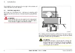
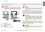
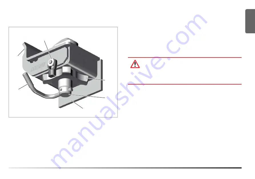
Operating equipment
3
6
1
2
5
4
TL403/003
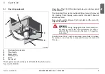
1
Pivot position indicator
2
Thrust plate
3
Safety catch
4
Clamping nut
5
Pivot
6
Rear panel
The diagram above shows the parts of the R 403 FR, which are also
found on the R 403 FL.
Operation of the R 403 FR as described below can also be applied
to the R 403 FL.
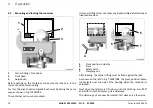
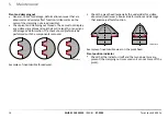
The integrated thrust plate provides additional security to prevent
the container from slipping; when used as intended it does not
absorb any forces.
A gap must be visible between the thrust plate and the corner fit-
ting of the container.
WARNING!
If the corner fitting is lying against the thrust plate (dur-
ing tipping), inspect the lock immediately for compli-
ance with the criteria set out in Chapter 5.1, "Inspection
A faulty corner fitting – with an excessively worn hole in the base,
for example – can cause the components to come into contact in
this way.
EN
Twist Locks R 403 Fx
MUB 013 005 M30
(REV-B)
07-2020
9


