background image

99744_UM_40S_G

23

For details see:

6 . 2 . 1   R E P L A C I N G   T H E   R E L E A S E   M E C H A N I S M   I N   F B 4 / F B H 4  
B R A C K E T   [ F I G .   5 ] .

The hydrostatic unit fitted on the float free bracket [FB4/FBH4] must be replaced
every 2. year. Marking on the hydrostatic unit show the expiry dateThe hydrostatic
comes complete with a new bolt and accessories.

1. Remove the EPIRB from its bracket by pulling out the locking pin on the clamp

and open the retaining rod that holds the beacon.

2. Unscrew the plastic bolt [FIG 5] (1) by screwing it counter clockwise and remove

the hydrostatic release mechanism [FIG 5] (2].

3. Check expiration date on the new hydrostatic release mechanism.The date

should be approximately 2 years from the date of purchase.

4. Mount the new hydrostatic release mechanism.The unit is fixed to the bracket

with a plastic bolt containing washer, rubber seal, washer, O-ring.

5. Secure the plastic bolt by hand force only!

6 . 2 . 2   R E P L A C I N G   T H E   R E L E A S E   M E C H A N I S M   I N   F B 5
B R A C K E T   [ F I G .   6 ] .

1. Release FB5 top cover by removing the locking split pin and special 

washer. [FIG. 6a] 

WARNING!  The EPIRB can drop out of the FB5 bracket when 

releasing top cover.

2. Press down the spring-loaded bracket plate and remove the hydrostatic 

unit by sliding it out of its locking slot. [Fig.6b]

3. Check the expiry date of the new hydrostatic release mechanism. [Fig.6c]

The date should be approximate two years from the date of purchase.

4. Install a new hydrostatic unit by pressing down the spring loaded bracket  

plate and sliding the unit into its locking slot. [Fig.6b]

5. Replace the EPIRB and the FB5 top cover.

Be sure that the top cover is locked at the bottom end and that
the top end are fixed at hydrostatic release mechanism rod.

Replace the special washer and the locking split pin. [Fig.6a]

6 . 2   H Y D R O S T A T I C   R E L E A S E   R E P L A C E M E N T

Summary of Contents for Tron 40S MkII

Page 1: ...www jotron com USERS MANUAL Tron 40S Cospas Sarsat 406MHz EPIRB...

Page 2: ...R STRING Continuous characters other than spaces in a message CHECKSUM The value sent with a binary coded message to be checked at the receiving end to verify the integrity of the message COSPAS COsmi...

Page 3: ...ition System GPS SYSTEM TIME Time corrected to Universal Time Coordinated UTC and used as the time standard by the user segment of the GPS system IEC International Electro technical Commission IMO Int...

Page 4: ...Satellite EPIRBs within 5 years if Passenger ships 12 passengers and cargo ships 300GT engaged in interna tional voyages shall perform Shore Based Maintenance SBM as follows Latest by the date of the...

Page 5: ...GE S VERSION REASON FOR CHANGE ES 22 03 06 32 pages F Kontroll med manualer doc ES 14 09 06 6 7 and 22 G New text A New manual B New text C New text D New text E New text 1 2 3 4 5 6 7 8 9 10 11 12 13...

Page 6: ...Jotron agents In addition to normal service Jotron agents have the necessary equipment and education to test the operational functions of the beacon Non original maintenance and or service parts may...

Page 7: ...RACKET MB5 AND MB4 18 4 4 MOUNTING THE FB5 MB5 FB4 FBH4 MB4 BRACKETS 18 5 OPERATING INSTRUCTIONS 19 5 1 MANUAL OPERATION 19 5 2 AUTOMATIC OPERATION 20 5 3 MANUAL TEST OF THE EPIRB 20 6 MAINTENANCE AND...

Page 8: ...A I D M E A S U R E S In case of contact of cell contents with eyes flush immediately with water for 15 min With skin wash with plenty of water and take off contaminated clothes If inhalation remove f...

Page 9: ...ified recorded in the radio log and brought to the attention of the Administration in compliance with the Radio Regulations together with an appropriate extract from the radio log STCW Code B VIII 2 N...

Page 10: ...resolved and you no longer require assistance contact the nearest search and rescue authorities via the most expeditious means available with the following information Beacon ID number 15 character UI...

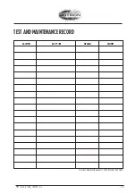
Page 11: ...11 99744_UM_40S_G DATE N T B SIGN INSP N NEW EPIRB INSTALLED T TEST B NEW BATTERY TEST AND MAINTENANCE RECORD...

Page 12: ...asing it from its bracket and then activate it Five different brackets are currently available for theTron 40S MB4 and MB5 is the manual bracket and FB4 and FBH4 is the automatic bracket FB5 is automa...

Page 13: ...n analogue signal is emitted on 121 5 MHz and a digital signal is transmitted on 406 025 MHz After theTron 40S is activated the next passing satellite will detect the transmitted signal and relay it t...

Page 14: ...data is correct in the shipping register or in the EPIRB data base Tron 40S purchased in some countries will have a registration form attached to it it is important that this registration form is comp...

Page 15: ...arbonate w 10 glassfibre Dimensions Height 379 mm Max diameter 180 mm Weight app 2 0 kg Materials Polycarbonate Compass safe distance 1 5 m Temperature range 20o C to 55o C Operating life Minimum 48 h...

Page 16: ...tween the two external electrodes sea water contacts When the Tron 40S is mounted in the automatic release bracket mechanism there is a safety switch in the EPIRB module a reed contact activated by a...

Page 17: ...ted by a magnet in the release mechanism This is the safety switch which prevent the seawater contacts to activate the beacon while placed in the release mechanism There is a brass weight which gives...

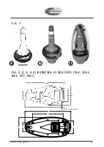
Page 18: ...chemicals oil exhaust and vibrations The location must also be easily accessible for testing and maintenance 4 2 FLOAT FREE BRACKET FBH4 See fig 8 for installation The float free bracket FBH4 must be...

Page 19: ...t holds the beacon Tie the beacon lanyard to you or to the survival craft and then follow instruc tions 1 to 6 or put beacon in the water to activate it It is not recommended to operate the beacon ins...

Page 20: ...he EPIRB to the TEST position Keep hands and other objects away from the upper part of the EPIRB away from the antenna 2 A successful test will consist of a series of blinks on the LED test indicator...

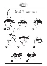
Page 21: ...ew one The battery module consists of the complete lower half of theTron 40GPS and is to be replaced every 5 year The marking on the battery module show the expiry date A new battery comes complete an...

Page 22: ...d on a voluntary basis by professionals Lithium batteries should have their terminals insulated prior to disposal 6 1 4 I N C I N E R AT I O N Incineration should never be performed by battery users b...

Page 23: ...lt containing washer rubber seal washer O ring 5 Secure the plastic bolt by hand force only 6 2 2 R E P L A C I N G T H E R E L E A S E M E C H A N I S M I N F B 5 B R A C K E T F I G 6 1 Release FB5...

Page 24: ...utput power and phase lock is tested During the test of the 406MHz transmitter a test message is transmitted this test message is coded with a special synchronization code and will not be recognized a...

Page 25: ...ations are shown 1 Flashing LED for 15 sec followed by one 1 flash no Xenon flash Error Low power on 406 MHz transmitter 2 Flashing LED for 15 sec followed by two 2 flashes no Xenon flash Error Low ba...

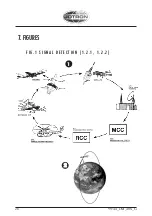
Page 26: ...26 99744_UM_40S_G 2 2 F I G 1 S I G N A L D E T E CT I O N 1 2 1 1 2 2 1 7 FIGURES...

Page 27: ...99744_UM_40S_G 27 F I G 2 M A N U A L O P E R AT I O N 5 1 1 1 3 2 ON READY TEST ON READY TEST ON READY TEST PUSH PUSH...

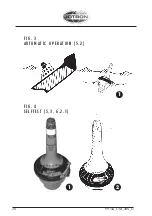
Page 28: ...99744_UM_40S_G 28 1 2 F I G 3 A U TO M AT I C O P E R AT I O N 5 2 F I G 4 S E L F T E S T 5 3 6 2 1 1 PUSH ON READY TEST...

Page 29: ...I G 5 R E P L A C I N G T H E R E L E A S E M E C H A N I S M I N F B 4 F B H 4 B R A C K E T 6 2 1 F I G 6 R E P L A C I N G T H E R E L E A S E M E C H A N I S M I N F B 5 B R A C K E T 6 2 2 F I G...

Page 30: ...30 99744_UM_40S_G 1 2 3 6 7 8 5 4 F I G 7 6 1 2 R E P L A C I N G T H E B AT T E RY M O D U L E...

Page 31: ...1 99744_UM_40S_G 9 10 F I G 8 2 4 4 4 M O U N T I N G O F B R A C K E TS F B 4 F B H 4 M B 4 F B 5 M B 5 66 2 91 2 326 9 422 0 28 136 5 209 3 F I G 7 M6 4X mounting hole PUSH 11 91 2 136 6 220 495 327...

Page 32: ...99744_UM_40S_G 32 NOTES...

Page 33: ...33 99744_UM_40S_G NOTES...

Page 34: ...Northumberland NE23 1LA United Kingdom Tel 44 1670 712000 Fax 44 1670 590265 E mail sales jotron co uk JOTRON Asia Pte Ltd Changi Logistics Center 19 Loyang Way 04 29 Singapore 508724 Tel 65 65426350...

Page 35: ...Jotron AS P O Box 54 NO 3280 Tjodalyng Norway Tel 47 33 13 97 00 Fax 47 33 12 67 80 www jotron com...

Reviews: