background image

15

139405_A  CF 

3

 BF 

3


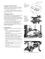
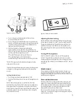
3.  Push in the gas control knob (B) a little and turn 

counter-clockwise to “PILOT”.

4.  Push in the gas control knob (B) as far as possible and 

hold it in. Simultaneously, push in the ignition knob (A) 

until the spark ignites the pilot flame located to the 

right rear corner of the burner..

5.  Continue to hold in the gas control knob for 

approximately 20 seconds after the pilot flame has 

been lit. Then let go of the knob. It should pop back out 

and the pilot flame should remain lit.

  If the pilot flame goes out, repeat Steps 1-5.
  If the pilot light goes out intentionally or 

unintentionally, it should not be relit within 3 minutes.

*NOTE: If the gas control knob does not pop out when 

released, call for service.

**NOTE: If the pilot flame does not remain lit after several 

attempts, turn the gas control knob to OFF and call for 

service.

Lighting the Main Burner

1.  Turn the gas control knob clockwise to “ON”.
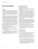
2.  Push the ON/OFF switch at the rear of the appliance to 

“ON”.

NOTE:  When the appliance is used for the first time, 

condensation may form in the firebox. Some smoke may 

also appear from the appliance during the initial hours, 

due to the burning off of paint and lubrication used in the 

production process. See section Odours when using the 

stove for the first time.

Adjusting the Heat Setting

Heat and flame size can be adjusted by turning the regu-

lator knob (C) marked “HI, LOW”, which is located next to 

the gas control knob (see fig. 

20)

. Maximum flame size 

provides maximum heat. Make sure the appliance has 

been operating for at least 30 minutes before adjusting 

the flame.

Turning Off the Appliance

Push the ON/OFF switch at the rear of the appliance 

to”OFF”. The pilot flame will continue to burn. In order 

to fully extinguish the appliance, push in the gas control 

knob (B, fig. 

20

) a little and turn clockwise to”OFF”.  Do not 

use force.

E

A

C

D

B

Maintenance

The complete installation, which includes the gas sup-

ply, the actual appliance and the vent system, must be 

inspected annually. The inspection must be carried out by 

qualified service engineer.

External Maintenance

Painted products may change color after some years of 

usage. The surface should be cleaned and brushed free 

of any loose particles before new stove paint is applied. 

Enameled products must only be cleaned with a soft 

damp cloth and only the surface is cold.
Do not use water or soap. Enamel surfaces stain easily 

when hot.  A solution of vinegar and baking soda may be 

used to remove stains.

Figure 20. Valve Controls.

Figure 21. Burner Control Switch.

Summary of Contents for GF 3 BF

Page 1: ...e or other flammable vapors and liq uids in the vicinity of this or any other appliance WHAT TO DO IF YOU SMELL GAS Do not try to light any appliance Do not touch any electrical switch do not use any...

Page 2: ...ssociated with the repair of gas controls plumb ing burners log set or sheet metal firebox beyond the warranty period 5 Damage caused by unauthorized modification use or repair 6 Damage to enameled su...

Page 3: ...6 5 User Information 14 6 Troubleshooting 16 7 Parts Illustrations and Lists 19 8 Service Record 23 THIS OWNER S MANUAL PROVIDES INFORMATION TO ENSURE SAFE INSTALLATION AND EFFICIENT DEPENDABLE OPERA...

Page 4: ...Burner Injector Marking 39 53 Pilot Injector Marking 51 30 Maximum Gas Consumption at Full Rate m3 h at 15 C 1013 25mbar 0 714 0 282 Maximum Gas Consumption at Full Rate kg h at 15 C 1013 25mbar 0 53...

Page 5: ...trol cover and control switch Care should be taken not to touch unit when it is in operation WARNING If you detect an odour of gas Do not light the Stove or any other appliance Do not use electrical s...

Page 6: ...d on carpet vinyl linoleum or other combus tible material Minimum dimensions of the floor plate 580 x 435 mm as in fig 2 J tul can supply floor plates in a variety of colors Firewall Requirements The...

Page 7: ...erminal which is supplied attached with 600mm of flue pipe The 600mm terminal section may be cut to up to 300mm if required 2 Flue arrangement for horizontal termination Fig 6b When the horizontal len...

Page 8: ...ations 400mm Max This arrangement can only be made using kit M82671 The maximum permissible horizontal length is 400mm This length is supplied attached to the terminal Fig 6 a Fig 6 b Fig 6 c Fig 6 d...

Page 9: ...ngth is 600mm or less Vent restrictor position is D 2 Flue arrangement for horizontal termination when horizontal length is greater than 600mm Vent restrictor position is D 3 Flue arrangement for vert...

Page 10: ...the peg as in fig 11 3 Place the left log on the pegs as in fig 12 4 Install middle log on the appropriate pegs shown in fig 13 5 Position embers loosely and maintain 6 mm clearance from the burner sk...

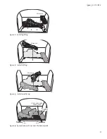
Page 11: ...gure 11 Install right log Figure 12 Install left log Figure 13 Install middle log 1 4 6 mm 1 4 6 mm Pilot Assembly KEEP CARRY OVER PORTS CLEAR PN 220730 PN 220728 PN 220729 Figure 14 Spread ember ston...

Page 12: ...con nected to the appliance open the gas supply and light the appliance see lighting instructions Perform a tightness test on all the pipe connections Commissioning Testing Gas Pressure Correct gas p...

Page 13: ...Flame above 2 Cleaning the glass 3 The gasket around the glass must be inspected annu ally for wear and replaced if necessary 4 Check if the textured embers need to be replaced 5 Look for soot It cou...

Page 14: ...t the appliance may emit a harmless non toxic odour It is recommended that the room should be thoroughly ventilated by opening doors or windows during first time use The gas is not toxic but the room...

Page 15: ...paint and lubrication used in the production process See section Odours when using the stove for the first time Adjusting the Heat Setting Heat and flame size can be adjusted by turning the regu lato...

Page 16: ...t a metal piece and the control knob red mark on the spark igniter is finally pushed to the bottom B If not replace the Piezo spark ignitor Fuel Gas Correct gas pressure is important see the section a...

Page 17: ...r the valve even if the pressure is OK at outlet E You should therefore always check for leakage Thermocouple Fig 23 and Thermopile Fig 24 A thermocouple is in principle a thermal generator and consis...

Page 18: ...he ON OFF STAT switch is connected 10 Turn the control knob on the valve to ON and turn the ON OFF STAT switch to ON At this point the multi meter should show more than 300 mV 11 If a thermostat or re...

Page 19: ...3 Figure 26 NOTE THE GAS CONTROL VALVE ASSEMBLY IS MOUNTED AT THE CENTER FRONT OF ALL STOVES NOTE THE GAS CONTROL VALVE ASSEMBLY IS MOUNTED AT THE CENTER FRONT OF ALL STOVES J tul GF 3 BF 3 Illustrat...

Page 20: ...Block 220614 20 Gas Line 5 16 x 18 Flex 154372 21 Orifice Holder Straight 129643 22 Glass Gasket Replacement Kit 155599 23 Glass Panel Ceramic 220576 24 Glass Gasket 7 16 Tadpole 6 ft 129124 25 Glass...

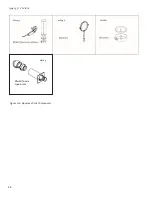
Page 21: ...21 139405_A CF 3 BF 3 Figure 27 Approved Vent Components M82678 M82652 M82650 M82653 M82654 M82668 M87379 M87913 M82656 M82657 M30170 M82667...

Page 22: ...22 139405_A CF 3 BF 3 100 170mm L 400mm Figure 27a Approved Vent Components M82655 M82671 M87196 M82661...

Page 23: ...ervice year 4 Sign Company Date Service details Annual service year 5 Sign Company Date Service details Annual service year 6 Sign Company Date Service details Annual service year 7 Sign Company Date...

Page 24: ...continual product development Consequently products may differ in speci fication color or type of accessories from those illustrated or described in various publications March 9 2011 139405_A J tul A...

Reviews: