27
139775_R
03
GI 535 DV IPI June 2016
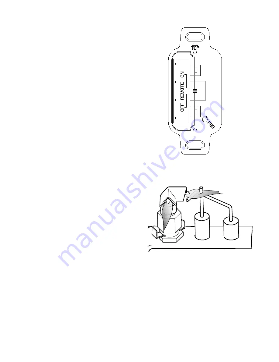
Figure 8.5. Correct Pilot Flame Pattern.
8.2 Fireplace Operation
8.2.1 Burner Switch
•
ON : Power is available to the Burner(s) only. They
will ignite at the last previous flame level setting.
•
REMOTE : Power is available for all appliance features.
•
OFF: The Burner will not operate.
8.2.2 Pilot Modes
•
Continuous Pilot Ignition ( CPI )
This permits the pilot to continue burning even
when there is no call for heat. This feature allows the
burner to function properly under a variety of adverse
conditions. For example, it can be difficult to establish
positive draft through a very long vent system,
particularly in very cold weather. In such cases, the
entire system will benefit as the heat generated by a
continuous pilot flame will help establish a positive
draft. CPI mode will also reduce glass condensation
upon start-up.
Exercise caution when operating with a continuous
pilot. DO NOT USE CLEANING PRODUCTS HAVING
COMBUSTIBLE VAPORS AROUND THE OPERATING
FIREPLACE.
•
Intermittent Pilot Ignition ( IPI )
This feature allows the pilot flame to go out
when there is no call for heat. Ideal for use with
thermostatic or manual remote control, the
Integrated Fireplace Control (IFC) module ignites
the pilot flame only when there is a call for heat. A
battery back-up permits continued functionality in
the event of a power failure.
Pilot Flame Appearance
The pilot flames should be blueish-yellow in color
and extend approximately 1” (25 mm) over to the
burner ports and flame sensor. Each flame should be
strong and steady - not fluttering or lifting. See fig.
8.5
8.2.3 Accent Lamp
The Accent Lamp is controlled by the hand-held remote
transmitter. See figs. 8.23-8.24, page 31.
Heat generated from the accent lamp may assist
in maintaining draft in very long vent runs and thereby
help ensure consistent IPI start-up performance.
8.2.4 Blower Function
An integral 120 cfm blower assists in moving heat
into the living environment. Power is supplied through
the same circuit used by the other fireplace components.
The blowers must be electrically grounded in accordance
with local codes, or, in the absence of local codes, with
the current NFPA 70 - National Electrical Code or CSA
C22.1 - Canadian Electrical Code.
The blower is controlled by the hand-held remote
transmitter. See fan control page 31, figs. 8.21-8.22.
Figure 8.4.
Burner control switch and remote initialization button.


