background image

12


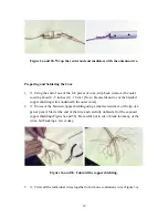
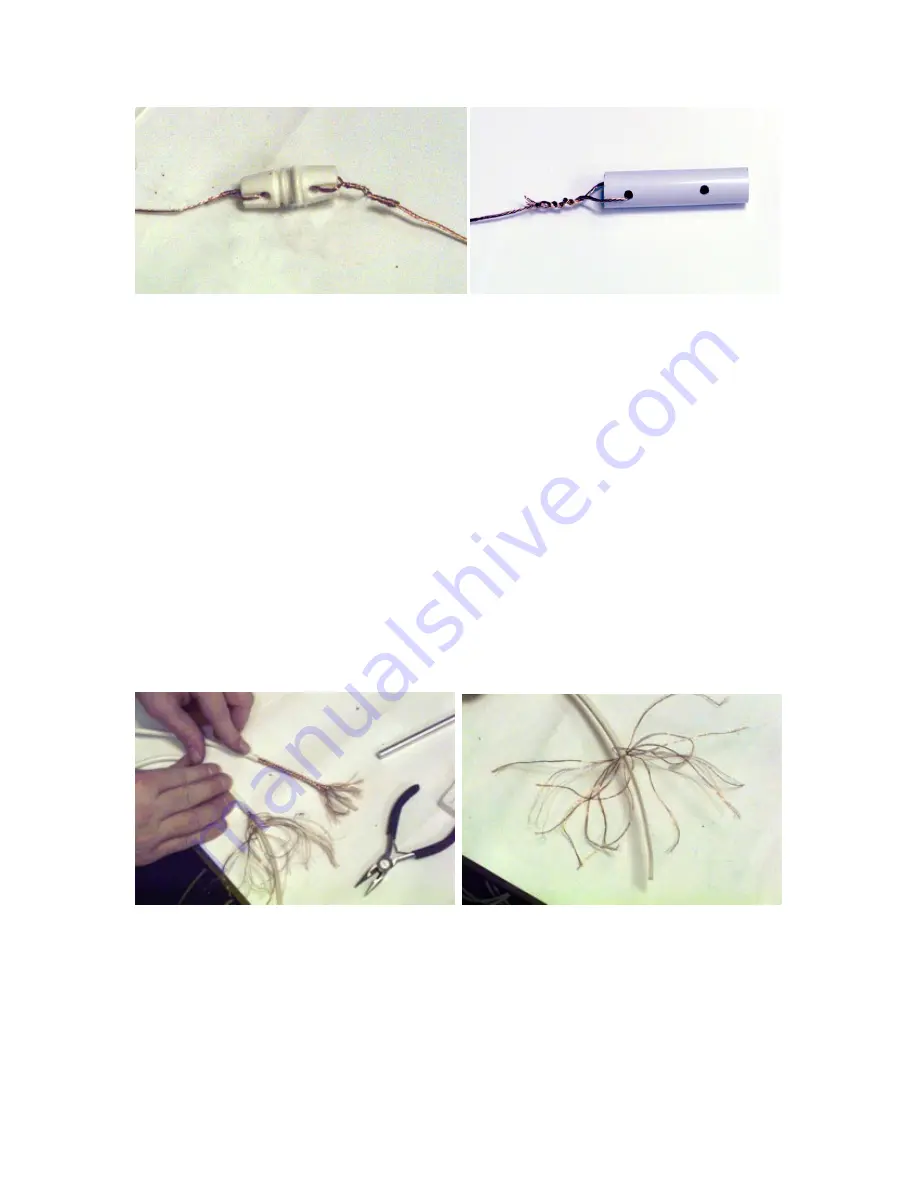
Figure 2a and 2b. Wrap the center and end insulators with the antenna wire.

Preparing and Soldering the Coax

1.


o


Using the end of one of the 

λ

/2 pieces of coax, strip back (remove) the outer

covering about 4 - 5 inches (10 - 12 cm). [Note: Be careful not to cut the braided

copper shielding wires underneath the outer cover].

2.


o


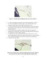
Unweave the braided copper shielding using a small screwdriver or the tip of a

pen or pencil. Start at the end of the wire and carefully unbraid all of the exposed

copper shielding (Figure 3a and 3b). Be careful not to cut or break too many of the

wires, but breaking a few is okay.


Figure 3a and 3b. Unbraid the copper shielding.

3.


o


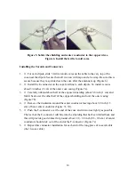
Twist all the individual wires together to form one continuous wire (Figure 3c).

Summary of Contents for RJ1.1

Page 1: ...JOVE RJ1 1 Antenna Kit Assembly Manual...

Page 2: ...VE RJ1 1 Antenna Kit Assembly Manual March 1999 Antenna Kit and Manual Developed for NASA Radio JOVE Project by Chuck Higgins Francisco Reyes Wes Greenman Jim Gass Thomas D Carr And the Radio JOVE Pro...

Page 3: ...2...

Page 4: ...3 Contents Theory of Operation 5 Site Requirements 5 Time Requirements 5 Dipole Array Schematic 6 Components 8 Tools 10 Parts List 10 Assembly 11 Field Setup 17...

Page 5: ...4...

Page 6: ...nimum requirements are a 25 x 35 ft flat area that has soil suitable for putting stakes into the ground Since the antenna system is sensitive to noise it is best not to set it up near any high tension...

Page 7: ...6...

Page 8: ...7...

Page 9: ...Since the Radio JOVE receiver is tuned to the frequency of 20 1 MHz M mega 106 the wavelength is 48 968 feet 14 925 meters A useful formula for calculating the half wavelength for an ideal dipole in f...

Page 10: ...s the connectors used for the Radio JOVE are called F type connectors and can be manually twisted onto the ends of the coax line These connectors are used to connect the cables to the power combiner a...

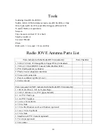
Page 11: ...m 14 Gauge Bare Copper Wire 7 stranded 1 70 ft 21 336 m RG59U Coaxial Cable Beldon 8241 4 PVC End Insulators cylinders 2 Plastic Center dogbone insulators 4 Twist on F connectors 1 Power combiner spl...

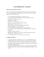
Page 12: ...2 sections of the coaxial cable to 2 16 2 ft 4 94 m Use the formula above for the ideal antenna wavelength and calculate 2 for the coaxial cable 2 coax 24 48 ft or 24 ft 5 in Multiply by the velocity...

Page 13: ...copper shielding wires underneath the outer cover 2 o Unweave the braided copper shielding using a small screwdriver or the tip of a pen or pencil Start at the end of the wire and carefully unbraid a...

Page 14: ...solder joints will not break 6 o Wrap the bare center conductor around the end of one of the copper wires attached to the center insulator Wrap the twisted shielding around the other copper wire attac...

Page 15: ...Figure 7a 3 o Carefully unbraid about half of the exposed shielding about 3 8 inch 1 cm and fold it back over the other half of the copper shielding and over the outer casing Figure 7b 4 o Remove the...

Page 16: ...t 3 05 m poles If the PVC is cut then four poles will be the top masts and four poles will be the bottoms 2 o Drill holes for the bolts and wires i Drill 1 4 in hole 2 inches 5 1 cm from the top of al...

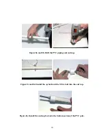
Page 17: ...6 Figure 8a and 8b Drill the PVC piping and end cap Figure 8c and 8d Install the eyebolt and the 3 8 in bolt into the end cap Figure 8e Install the end cap foot onto the bottom section of the PVC pole...

Page 18: ...d leave about 1 foot between the insulator and the top of the pole Field Setup Setting up the Antenna 1 o Lay out each dipole antenna flat on the ground with the ends of each dipole facing in the EAST...

Page 19: ...gging Do not tighten the guy wires too tight because this will cause undue stress on the dipole antenna 5 o At a North South distance of 20 ft 7 6 m from the first dipole repeat steps 2 4 and set up t...

Page 20: ...19 Figure 9e and 9f Lori and Kia help set up the antenna Figure 9g and 9h JOVE receiver setup with computer...

Page 21: ...20 Figure 9i and 9j JOVE receiver connections and setup with tap recorder Figure 9k and 9l Kia checks the equipment at NASA s Goddard Space Flight Center...

Page 22: ...e power combiner on the twin side by screwing on each F connector to the threads of the combiner Figure 9f 2 o Connect the 1 coaxial cable long coax to the single side of the power combiner 3 o Connec...

Reviews: